Download
1 / 83
1.06k likes | 1.49k Views
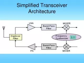
Simplified Transceiver Architecture. HPMX-2007. The lkhefw wlkhq wilehr. The lkhefw wlkhq wilehr. The lkhefw wlkhq wilehr. wejklh wajkhrqwilu wae. wejklh wajkhrqwilu wae. wejklh wajkhrqwilu wae. esjlkh qwh wlh lihewrw. esjlkh qwh wlh lihewrw. esjlkh qwh wlh lihewrw.

E N D
HPMX-2007 The lkhefw wlkhq wilehr The lkhefw wlkhq wilehr The lkhefw wlkhq wilehr wejklh wajkhrqwilu wae. wejklh wajkhrqwilu wae. wejklh wajkhrqwilu wae. esjlkh qwh wlh lihewrw esjlkh qwh wlh lihewrw esjlkh qwh wlh lihewrw wklhjr qlih qilh q q3wih q wklhjr qlih qilh q q3wih q wklhjr qlih qilh q q3wih q wejklh wajkhrqwilu wae. wejklh wajkhrqwilu wae. wejklh wajkhrqwilu wae. esjlkh qwh wlh lihewrw esjlkh qwh wlh lihewrw esjlkh qwh wlh lihewrw wklhjr qlih qilh q q3wih q wklhjr qlih qilh q q3wih q wklhjr qlih qilh q q3wih q wejklh wajkhrqwilu wae. wejklh wajkhrqwilu wae. wejklh wajkhrqwilu wae. esjlkh qwh wlh lihewrw esjlkh qwh wlh lihewrw esjlkh qwh wlh lihewrw wklhjr qlih qilh q q3wih q wklhjr qlih qilh q q3wih q wklhjr qlih qilh q q3wih q wejklh wajkhrqwilu wae. wejklh wajkhrqwilu wae. esjlkh qwh wlh lihewrw wklhjr qlih qilh q q3wih q esjlkh qwh wlh lihewrw wklhjr qlih qilh q q3wih q wejklh wajkhrqwilu wae. wklhjr qlih qilh q q3wih q esjlkh qwh wlh lihewrw wklhjr qlih qilh q q3wih q wklhjr qlih qilh q q3wih q wklhjr qlih qilh q q3wih q wejklh wajkhrqwilu wae. wejklh wajkhrqwilu wae. wejklh wajkhrqwilu wae. esjlkh qwh wlh lihewrw esjlkh qwh wlh lihewrw esjlkh qwh wlh lihewrw wklhjr qlih qilh q q3wih q wklhjr qlih qilh q q3wih q wklhjr qlih qilh q q3wih q wejklh wajkhrqwilu wae. wklhjr qlih qilh q q3wih q wejklh wajkhrqwilu wae. esjlkh qwh wlh lihewrw wejklh wajkhrqwilu wae. esjlkh qwh wlh lihewrw wklhjr qlih qilh q q3wih q esjlkh qwh wlh lihewrw wklhjr qlih qilh q q3wih q wklhjr qlih qilh q q3wih q wklhjr qlih qilh q q3wih q wejklh wajkhrqwilu wae. wejklh wajkhrqwilu wae. esjlkh qwh wlh lihewrw uP/ DSP A A D D Q Data I Data Power Supply Transceiver Role of a Transmitter Information 2. add data to carrier 3. shift to high frequency Modulator Mixer 0 90 Antenna Baseband Processor Power Amplifier 4. amplify to broadcast Oscillator bias bias 1. create carrier
HPMX-2007 The lkhefw wlkhq wilehr The lkhefw wlkhq wilehr The lkhefw wlkhq wilehr wejklh wajkhrqwilu wae. wejklh wajkhrqwilu wae. wejklh wajkhrqwilu wae. esjlkh qwh wlh lihewrw esjlkh qwh wlh lihewrw esjlkh qwh wlh lihewrw wklhjr qlih qilh q q3wih q wklhjr qlih qilh q q3wih q wklhjr qlih qilh q q3wih q wejklh wajkhrqwilu wae. wejklh wajkhrqwilu wae. wejklh wajkhrqwilu wae. esjlkh qwh wlh lihewrw esjlkh qwh wlh lihewrw esjlkh qwh wlh lihewrw wklhjr qlih qilh q q3wih q wklhjr qlih qilh q q3wih q wklhjr qlih qilh q q3wih q wejklh wajkhrqwilu wae. wejklh wajkhrqwilu wae. wejklh wajkhrqwilu wae. esjlkh qwh wlh lihewrw esjlkh qwh wlh lihewrw esjlkh qwh wlh lihewrw wklhjr qlih qilh q q3wih q wklhjr qlih qilh q q3wih q wklhjr qlih qilh q q3wih q wejklh wajkhrqwilu wae. wejklh wajkhrqwilu wae. esjlkh qwh wlh lihewrw wklhjr qlih qilh q q3wih q esjlkh qwh wlh lihewrw wklhjr qlih qilh q q3wih q wejklh wajkhrqwilu wae. wklhjr qlih qilh q q3wih q esjlkh qwh wlh lihewrw wklhjr qlih qilh q q3wih q wklhjr qlih qilh q q3wih q wklhjr qlih qilh q q3wih q wejklh wajkhrqwilu wae. wejklh wajkhrqwilu wae. wejklh wajkhrqwilu wae. esjlkh qwh wlh lihewrw esjlkh qwh wlh lihewrw esjlkh qwh wlh lihewrw wklhjr qlih qilh q q3wih q wklhjr qlih qilh q q3wih q wklhjr qlih qilh q q3wih q wejklh wajkhrqwilu wae. wklhjr qlih qilh q q3wih q wejklh wajkhrqwilu wae. esjlkh qwh wlh lihewrw wejklh wajkhrqwilu wae. esjlkh qwh wlh lihewrw wklhjr qlih qilh q q3wih q esjlkh qwh wlh lihewrw wklhjr qlih qilh q q3wih q wklhjr qlih qilh q q3wih q wklhjr qlih qilh q q3wih q wejklh wajkhrqwilu wae. wejklh wajkhrqwilu wae. esjlkh qwh wlh lihewrw uP/ DSP A A D D Q Data I Data Power Supply Role of a Receiver Information 4. discard carrier and recover data 2. shift to lower frequency (cost and/or performance) De-Modulator Baseband Processor Mixer 0 90 Antenna Low Noise Amplifier 1. amplify received signal with min. added noise Oscillator bias bias bias 3. LO for down conversion
Mixer = Multiplying up/down conversion • Frequency translation device • Ideal mixer: • Doesn’t “mix”; it multiplies AB A B
Image problem converting to IF A has desired signal at wIF A1cos(wRFt) plus an interference at wIM A2cos(wIMt) B is at wLO And: wRF - wLO = wLO - wIM = wIF Both converted to IF, Can’t be cleaned once corrupted
Problem of Image Signal • Solution: Image Rejection Filter
Problem of Half IF • Second order harmonic
Multi IF Stage Receivers • Received RF signal is down converted stage by stage until the desired final IF is obtained • Frequency conversion ratio of each stage is usually kept lower than 10. • For example, RF 1800 MHz IF1 450 MHz, then IF290 MHz, and finally IF3 18 MHz. • Corresponding ratios are: 4; 5; 5; total 100. • Each stage has it’s own image problem • Each stage requires demanding filtering • Typically done off chip or using SAW • Complicated, bulky, expensive
IF and LO frequency selection • Fixed RF filter before LNA for band selection • One for each standard • Off-chip, high quality, no freedom • IF frequency is selected at design • Fixed for each product • LO frequency is tuned in real time • |RF–LO|=IF • Actual RF freq depends on which channel is assigned to device • LO tuning range must cover RF bandwidth
Selection of IF • If IF is large, • better separation between RF and image • better image rejection • easier image rejection filter design • More stages of down conversion • Other IF selection criteria • Select IF so that image freq is outside of RF band • IF >= (RF BW)/2 • Sometime may not be possible, if (RF BW)/2 is within RF Band
For each channel assignment, there are two choices of LO freq that meets the requirement |RF–LO|=IF. • Q: should LO > RF, or LO < RF??
Example: AM Radio • AM radio band: 530 to 1610 KHz • BW/2 = (1610-530)/2=1080/2=540, in band • IF has to be lower. Commonly: 455kHz • Image can be in AM band • If LO is on low side, LO tuning range is: • (530 to 1610) – 455 = (75 to 1155) • LO lowest to highest is a factor of 15.4 • If LO is on high side, LO tuning range is: • (530 to 1610) + 455 = (985 to 2065) • LO lowest to highest is a factor of 2.01
Direct Conversion Receiver No image problem
Direct Conversion Receiver LO is at same frequency as RF 1/f noise here can end up in channel Self mixing cause DC problem - Quadrature RF down conversion required - DC problem - Typically requires offset or 2x LO to avoid coupling + Eliminate IF SAW, IF PLL and image filtering + Integration + Avoids image problem
DC Offset (Self-mixing) A D w c 0 Saturates the following stages capacitive coupling substrate coupling bondwire coupling aLO(t)=ALOcos(w c+q) w c A D w c 0 w c
DC Offset (Self-mixing) + level DC Offset t -
-A DC Offset Cancellation • Capacitive Coupling • Requires a large capacitor • Negative Feedback • Nonlinear • TDMA Offset Cancellation • Requires a large capacitor
1/f noise effect • CMOS transistors has significant 1/f noise at low to DC frequency • Significantly noise performance of direct conversion receivers Receive signal 1/f noise f
Even-Order Distortion Direct feed through Direct feed through
Mirror Signal • Upper sideband and lower sideband are identical
Mirror Signal • Upper sideband and lower sideband are not identical
Mirror Signal Suppression • Quadrature Down Conversion ui(t) vi(t) A I D 0 90 a(t) Q A D vq(t) uq(t)
Phase & Gain Error I 0 Phase & Gain Error 90 a(t) Q Phase & Gain Error I/Q Mismatch
Phase error Gain error Effect of phase mismatch Effect of gain mismatch
Use of I/Q down conversion recovers the nonsymmetrical receive signal spectrum But port isolation becomes more challenging Selfmixing and even order distortion may affect both channels and affect each other, causing additional I/Q mismatch
DC and 1/f cancellation Base Band DSP A/D 0 90 a(t) A/D Phase and gain mismatch compensation
Summary of Direct Conversion Receiver • No need for imager reject filter • Suitable for monolithic integration with baseband • DC offsets due to crosstalk of input ports of mixer • Even order IM direct feed through to baseband • Quadrature down conversion suppresses mirror • I/Q mismatch due to mismatches in parasitics • Low power consumption attributes to less hardware
Low IF receiver • - Quadrature RF down conversion required • - Require higher performance ADC • Additional mixer • Slower RF PLL settling • Even order distortion still problem • Low freq IF filters require large chip area + Eliminate IF SAW, IF PLL and image filtering + Integration + Relaxes image rejection requirements + Avoids DC problems, relaxes 1/f noise problem
Low-IF Down Conversion Complex BPF Mirror signal, needs removal
Mirror Signal Suppression (1) Complex Bandpass Filter I Q I Q LO1 LO2
Mirror Signal Suppression (2) I Q Q I LO1 LO2 Both schemes used in heterodyne receivers for image rejection Mathematical analysis very similar
Image rejection architectures • Use additional hardware (LO’s, mixers, and filters) • Use I/Q channels which process + or – frequencies differently • Two steps of I/Q to solve both image and mirror problems • Effects limited by I/Q channel/filter matching accuracies
Image Reject Receiver • Hartley Architecture A C -90° RF input IF output 0 w LO 90 B
Hartley Architecture xcos xsin
IQ error effect • Ideal IQ: image completely rejected • If signal and image not single tone, 90o shift is not exact • Local oscillator’s sine and cosine not matched in magnitude and phase • 90o phase shifter may have both gain and phase error • All lead to incomplete image rejection
Image Reject Receiver Hartley Architecture with simple 90 deg phase shiftor
Gain Mismatch due to R, C errors At w = 1/RC: