Download
1 / 16
160 likes | 321 Views
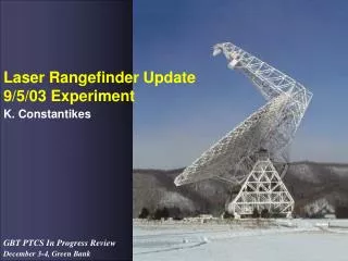
Laser Rangefinder Update 9/5/03 Experiment. K. Constantikes. Experiment. Designed to correlate thermal, astrometric data with LRF data ~24 hours of: Point/focus at source near NCP “Track” at 360 ° , 38 ° for 2 minutes LRFs running continously, 15 sec sample interval

E N D
Laser Rangefinder Update9/5/03 Experiment K. Constantikes
Experiment • Designed to correlate thermal, astrometric data with LRF data • ~24 hours of: • Point/focus at source near NCP • “Track” at 360°, 38° for 2 minutes • LRFs running continously, 15 sec sample interval • 11 targets, some with 4 rangefinders designated (FA tip, el bearing) • Zero points for each instrument • Leakages for each instrument • Weather data , 10 sec sample interval • LRFs had pointing optimized for all target at this GBT pose
Range data processing • Zero points and leakages smoothed: 75 sec median • Group refractive index smoothed: 120 sec median • LRF integration time 1 sec • SNR >= 10: Phase estimate noise ~<200 m • Selected low SNR to get more range data… • RMS range residual in trilateration will ID noisy range data • 97F Fem model used for range prediction and resolving range uncertainty • Ranges corrected for glass offset, GRI, monument and rangefinder geometry • For 4 el bearing targets (2 each side) and 2 FA tip targets: • Select last 60 secs of data (up to 4 ranges, 4 rangefinders), GBT at 360°, 38° 1” • ~< 650 m FA y, ~< 250 m FA x,z • ~< 125 m el bearing x,y
Bounding actual FA position errors 2.4” ~= 0.8mm at FA tip
Bounding actual el bearing position errors 3” at el bearing ~= 0.4mm
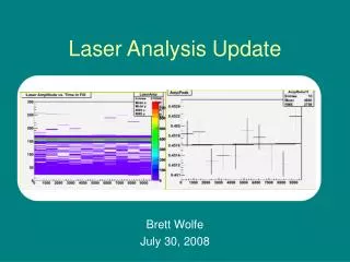
ZAG736D: The best • 1900 outage due to SW failure • Some trend visible in X • No data after ~2130 • LRF pointing • Dew, fog • Expectation of 1s range error ~40mm • 3 rangefinders • Consistent PTCS/PN/8
ZAG736D: The best ~ 25 minutes • - Dispersion of range error broader due to low SNR threshold. • 40mm * PDOP ~ 300mm total position error SHORT TERM (60 secs) ? • Actual 1s total position error ~ 2mm, 1s y error ~0.7mm, or ~ 6” azimuth pointing error equiv.
ZEG41040L: Monument errors • No data after ~2100 • Position jumps due to redundant ranging (4 LRFs) and monument posn errors • Consistent with ~1 mm monument posn error. X (mm) Number of LRFS
ZY107: Erratic pointing • Very high SNR occasionally, but long outages
ZY102: Low laser power? • Consistent SNR • Degrade after sundown- • Dew? • Thermal pointing shift? • SNR would be still be adequate @ 0.1sec integration • 1900 outage was software
ZY103: Inadequate laser power, poor pointing • Laser power too low for 0.1 sec integration time • Pointing erratic too…
Data quality statistics • 6 Targets, ~ 20 hours, 4 ranges per minute: • 2 retros per el bearing, 2 FA tip retros • Possible 20x60x4 = 4800 trilaterations • About half lost due to fog, dew • Others lost to pointing/SNR issues (even though SNR=10 threshold used) Total “good” trilaterations, percent excluding fog/dew: ZAG731D ………….210 or 10% ZAG731P ………….142 or 5% ZAG736D ………….611 or 25% ZAG736P ………….44 or 0% ZEG41040L ……….241 or 10% ZEG41040R ………337 or 15%
Reliability • Out of six experiments, not one case where all 12 ground LRFs were operational • ~ one week preparation time each case. • Pointing problems most common, but also • Oscillator failures • Servo failures • Computer (ZY and ZIY) failures
Fixes • LRF outgoing and incoming beams need to be broadened, pointing errors identified • Some laser diodes replaced (obsolete, will require mechanical retrofits • Other parts nearing obsolesence (IRIG, Oscillators…) • 360 Degree retros to improve ground geometry • Beam split and track to ameliorate detector group delay issues (centriod and carrier density)? • How to ameliorate dew problem? • More lab characterization to ensure we’re ready… Major, time consuming, expensive undertaking
Summary • Not only are there fundamental issues- • Geometry and group refractive index • And major system design issues- • E.g., LRFs on feed arm • But also suitability, usability, cost, and schedule issues. • And we know how to fix them…