Download
1 / 50
500 likes | 528 Views
This tutorial covers entity types, key attributes, value sets, ER diagrams, and relationships in the initial conceptual design of a company database. Learn to represent departments, projects, employees, and dependents using ER diagrams.

E N D
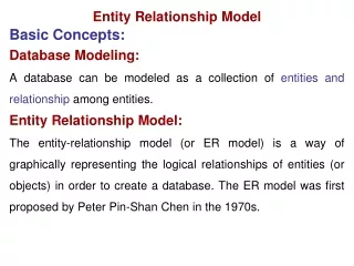
ENTITY-RELATIONSHIP MODEL DB:ER Model
Objectives • Entities and Attributes + • Initial Conceptual Design of the COMPANY Database + • Relationships + • Weak Entity Types + • Higher Degree Relationships + • Refining the ER Diagram for the COMPANY Database + • Summary of ER Diagram Notations + • Alternative Notations for ER Diagrams + DB:ER Model
- Entities and Attributes • Entity Types + • Entity Sets + • Key Attributes of an Entity Type + • Value Sets (Domains) of Attributes + • ER Diagrams for Entities and Attributes + DB:ER Model
-- Entity Types • A database usually contains groups of entities that are similar. • Example: A company employing many employees stores similar information about each employee. • Entity type: is a collection (or set) of entities that have the same attributes. • Example 1: Entity type EMPLOYEE has attributes such as • Name • DOB • Salary • Example 2: Entity type COMPANY has attributes such as • Name • Headquarters • President DB:ER Model
-- Entity Sets • The collection of all entities of a particular entity type in the database at any point of time is called entityset. • Entity types are also called the intensionand entity sets are called the extension. • An extension of the previous examples are shown below: DB:ER Model
-- Key Attributes of an Entity Type • An entity type usually has an attribute whose value is distinct for each individual entity in the collection. Such attribute is called a key attribute. • Example: SSN is a key for EMPLOYEE entity type. • If a set of attributes posses the above property then their combination is called a composite key. • An entity that has no key of its own is called a weakentity and will be discussed later. • Entity types must fulfill the key, or uniqueness, constraint on its attributes. DB:ER Model
-- Value Sets (Domains) of Attributes • Each Single attribute of an entity type is associated with a value set (or a domain of values) • This domain specifies the set of values that may be assigned to that attribute for each individual entity. • Examples of domains: • The domain of the Age attribute for the EMPLOYEE entity is the set of integers from 16 to 70. • The domain of the Name attribute for the EMPLOYEE entity is the set of strings of alphabetic characters separated by blanks. DB:ER Model
-- ER Diagrams for Entities and Attributes • ER diagrams are used to represent entity types, attributes of these types and the relationship between them. • In an ER diagram, an entity type is represented by a rectangular box enclosing the entity name. • Attribute names are enclosed in ovals and they are attached to their entity type by a strait line. • Composite attributes are attached to their attributes by straight lines. • Multi-valued attributes are enclosed by double ovals. • Key attributes of an entity are underlined in the ER diagram F. name M. Init Phone EMPLOYEE Name L. name Age SSN DB:ER Model
- Initial Conceptual design for the Company Database … • From the requirements of the company DB we can identify the following entities: • DEPARTMENT • PROJECT • EMPLOYEE • DEPENDENT • In the next few slides, we will show how the above four entities together with their attributes are represented using ER diagram. DB:ER Model
-- DEPARTMENT Entity Representation • An entity type DEPARTMENT has attributes: • Name (key) • Number (key) • Locations (multi-valued attribute) • Manager and • ManagerStartDate. Manager ManagerStartDate Name Locations DEPARTMENT Number DB:ER Model
-- PROJECT Entity Representation • An entity type PROJECT has attributes: • Name (key) • Number (key) • location • ControllingDepartment ControllingDepartment Name Location PROJECT Number DB:ER Model
-- EMPLOYEE Entity Representation • Entity Representation: • An entity type EMPLOYEE with attributes: Name, SSN, Address, Salary, BirthDate, Department, Supervisor, and WorksOn. WorksOn is multi-valued composite attribute (project, Hours). SSN is the key attribute. Both name and address can be composite attributes. F. name Address Supervisor Sex M. Init SSN EMPLOYEE Name BirthDate L. name Works_On Salary Department Hours Project DB:ER Model
-- DEPENDENT Entity Representation • An entity type DEPENDENT has attributes: • Employee • DependentName • Sex • BirthDate • Relationship BirthDate DependentName Employee Relationship DEPENDENT Sex DB:ER Model
- Relationships • Introduction to Relationship Types + • Relationship types and Instances + • Role names and Relation types + • Role names and Recursive Relationship types + • Constraints on Relationship Types + • Attributes of Relationship Types + • Relationship Representation in ER Diagram + • Higher Degree Relationships + • Examples + DB:ER Model
-- Introduction to Relationship Type • By reviewing the initial design of the COMPANY DB example we can see the following: • Some attributes of an entity reference other attributes in the same or other entities. For example, The attribute Department of the EMPLOYEE entity type refers to the DEPARTMENT entity that the employee works for. • These are implicit relationships that exist between entity types. • A better representation will be obtained if these are represented as relationships between the entity types rather than linking attributes. • Here we will describe another major component of ER model; namely relationships. • We will discuss relationship types, instances, degrees, and constraints on relationships. DB:ER Model
-- Relationship Types and Instances… • Informally, a relationship type is a meaningful association among entity types. • A relationship (instance) is an association of entities where the association includes one entity from each participating entity type. • Mathematically, a relationship type (set) R between entity types E1, E2, …, En is a set of relationship instance ri, where each ri associates n individual entities (e1, e2, …, en); and each entity ei, in ri, is a member of the entity type Ej, 1<= j <= n. • The degree of a relationship is the number of entity types participating in that relationship. DB:ER Model
… -- Relationship Types and Instances • For example, lets look ate the relationship type WORKS_FOR between the two entities EMPLOYEE and DEPARTMENT, which associates each employee with the department he works for. • Each relationship instance in the relationship set WORKS_FOR associates one EMPLOYEE entity and one DEPARTMENT entity as shown in the figure below. DB:ER Model
-- Role Names and Relation Types • Each entity type that participates in a relationship type plays a particular role in the relationship. • For example, in the WORKS_FOR relationship type, EMPLOYEE plays the role of employee or worker and DEPARTMENT plays the role of department. • In most of the cases, the name of the entity type can be used as the role name of that entity type in the relationship type it participates in, a shown in the previous example. DB:ER Model
-- Role Names and Recursive Relations … • In some cases, the same entity type participates more than once in a relationship roles. In such cases the role name becomes essential for distinguishing the meaning of each participation. Such relationship type are called recursive relationships. • For example, the SUPERVISOR relationship type relates an employee to a supervisor, and both belongs to the EMPLOYEE entity type, as shown in this figure. DB:ER Model
… -- Role Names and Recursive Relations EMPLOYEE SUPERVISION 1 e1 r1 1 2 e2 1 r2 2 e3 1 r3 2 r4 e4 2 … e5 … … … … 1: Supervises 2: Supervised DB:ER Model
-- Constraints on Relationship Types • Relationship types usually have some constraints that limit the possible combination of entities that may participate in the corresponding relationship set. These constraints are obtained from the mini-world situation that the relationship represents. • For example, if we have a rule in the COMPANY stating that an employee can work for one department only, then we should be able to represent this constraint. • Two main types of restrictions on relationships are: • cardinality and • Participation DB:ER Model
--- Cardinality (Ratio) Constraints • Determines the number of possible relationships for each participating entity. • For example, in the relationship type WORKS_FOR, the cardinality ratio of DEPARTMENT:EMPLOYEE is 1:N, meaning that each department can be related to many employees but an employee can be related to only one department. • Most common degree for relationships is binary with cardinality ratios of one-to-one (1:1), one-to-many (1:n), or many-to-many (N:M). DB:ER Model
---- One-to-many(1:N) or Many-to-one (N:1) RELATIONSHIP WORKS_FOR EMPLOYEE DEPARTMENT r1 r2 r3 r4 r5 r6 r7 e1 e2 e3 e4 e5 e6 e7 d1 d2 d3 DB:ER Model
--- Participation Constraints • Determines whether the existence of an entity depends on its being related to another entity through the relationship. • An entity is either totally or partially participating in a relationship. • For example, if the company policy states that each employee entity can exist only if it participates in a WORKS_FOR relationship instance. Thus, the participation of the employee entity in the relationship WORKS_FOR is total. Total participation is also called existence dependency. • However, only some employees manage departments in the company. Therefore, we say that the participation of the EMPLOYEE entity in the relationship MANAGES is partial. DB:ER Model
---- Example of Partial/Total Relationship MANAGES DEPARTMENT EMPLOYEE e1 d1 e2 r1 d2 e3 r2 r3 d3 e4 … e5 … … … … … … DB:ER Model
-- Attributes of Relationship Types • Relationship types can have their own attributes similar to the entity types. • For example, to record the number of hours per week that an employee works on a particular project, we can include an attribute Hours for the relationship type WORK_ON between EMPLOYEE and PROJECT entity types. • Another Example, is to include the date on which a manager starts managing a department via an attribute StartDate for the relationship type MANAGES between EMPLOYEE and DEPARTMENT entity types. DB:ER Model
-- Relationship Representation in ER Diagram • Relationship types can have their own attributes similar to the entity types. • For example, to record the number of hours per week that an employee works on particular object, we can include an attribute Hours for the relationship type WORK_ON between EMPLOYEE and PROJECT entity types. • Another example, is to include the date on which a manager starts managing a department via an attribute StartDate for the relationship type MANAGES between EMPLOYEE and DEPARTMENT entity types. StartDate 1 1 DEPARTMENT MANAGES EMPLOYEE DB:ER Model
-- Higher Degree Relationships • In many instances, it is required to represent relationship that is of a degree higher than 2 (HD), i.e. it involves more than two entity types. • Sometime these relationships can be represented using binary relations, although sometime this may not give the same meaning. • For example the tuple (s, p, j) which states that SUPPLIER s supplies PART p to PROJECT j may not be expressed by the three tuples (s,p), (s,j) and (p,j). DB:ER Model
--- Example: Higher Degree Relationships DB:ER Model
-- Examples • Example of Participation Constraint • Partial/Total Relationship • Examples of Cardinality Constraint • One-to-One • One-to-Many • Many-to-Many DB:ER Model
--- Partial/Total Relationship MANAGES DEPARTMENT EMPLOYEE e1 d1 e2 r1 e3 d2 r2 e4 r3 d3 e5 StartDate 1 1 DEPARTMENT MANAGES EMPLOYEE Partial participation Total participation DB:ER Model
---- One-to-One (1:1) Relationship WORKD_FOR DEPARTMENT EMPLOYEE d1 e1 r1 e2 r2 d2 e3 r3 d3 e4 r4 d4 e5 r5 d5 DEPARTMENT WORKS_FOR EMPLOYEE 1 1 Cardinality is 1:1 DB:ER Model
---- One-to-many(1:N) or Many-to-one (N:1) Relationship WORKD_FOR DEPARTMENT EMPLOYEE e1 r1 d1 e2 r2 d2 e3 r3 e4 r4 d3 e5 r5 DEPARTMENT WORKS_FOR EMPLOYEE N 1 Cardinality is N:1 DB:ER Model
---- Many-to-many (M:N) or Many-to-Many (N:M) Relationship WORKD_FOR DEPARTMENT EMPLOYEE e1 r1 d1 e2 r2 d2 e3 r3 e4 r4 d3 r5 DEPARTMENT WORKS_FOR EMPLOYEE M N Cardinality is M:N DB:ER Model
- Weak Entity Types … • An entity whose existence depends on some other entity type is called a weak entity type. Other wise it is called a strong entity type. • Entities belonging to a weak entity type are identified by being related to specific entities from another entity type in combination with some of their attribute values. • We call this other entity type identifying, or owner, entity type and we call the relationship that relates a weak entity type to its owner type the identifying relationship type of the weak entity type. DB:ER Model
… - Weak Entity Types • A weak entity type always has a total participationconstraint with respect to its identifying relationship type. • Weak entity types are uniquely identified by a partial key that will be added to the key of the strong entity type that it is associated with. In the ER digram a partial key is a dashed underline. • For example, in the COMPANY database, the DEPENDENT entity type dependes on the existence of the EMPLOYEE entity type, i.e. no dependent will exist in the database unless at least one of his/her parents works as an employee in the company. • The DEPENDENT entity type has the dependent name as a partial key that will be added to the SSN of the employee who is associated with, to uniquely identify the dependent. DB:ER Model
- Higher Degree Relationships • In many instances, it is required to represent relationship that is of a degree higher than 2 (HD), i.e. it involves more than two entity types. • Sometime these relationships can be represented using binary relations, although sometime this may not give the same meaning. • For example the tuple (s, p, j) which states that SUPPLIER s supplies PART p to PROJECT j may not be expressed by the three tuples (s,p), (s,j) and (p,j). DB:ER Model
Higher Degree Relationships DB:ER Model
- Refining The ER Diagram for the COMPANY Database … • Now we can refine the initial design of the COMPANY database using concepts of relationships that were introduced in the previous sections. • Revision will be made by placing the attributes that represent relationships into relationship types. • The cardinality ratio and participation constraints of each relationship type are determined from the initial requirements. If not stated then they should be obtained from the user. • In the COMPANY example we can determine the following relationship type: DB:ER Model
… - Refining The ER Diagram for the COMPANY Database … • MANAGES: • A 1:1 relationship type between EMPLOYEE and DEPARTMENT. • EMPLOYEE participation is partial. • The participation of DEPARTMENT is total. • The attribute StartDate is assigned to the relationship type. • WORKS_FOR: • A 1:N relationship type between EMPLOYEE and DEPARTMENT. • Both participations are total. • CONTROLS: • A 1:N relationship type between DEPARTMENT and PROJECT. • The participation of PROJECT is total. • The participation of DEPARTMENT is partial (was known after consulting with users. DB:ER Model
… - Refining The ER Diagram for the COMPANY Database … • SUPREVISION: • A 1:N relationship type between EMPLOYEE (in supervisor role) and EMPLOYEE (in supervisee role). • Both participations are partial, determined after consulting users. • WORKS_ON: • An M:N relationship type between EMPLOYEE and PROJECT. • Both participations are total. • The attribute hours is added to the relationship type. • DEPENDENTS_OF: • An 1:N relationship type between EMPLOYEE and DEPENDENT. • The participation of EMPLOYEE (the identifying entity) is partial • The participation of DEPENDENT (the weak entity) is total. DB:ER Model
… - Refining The ER Diagram for the COMPANY Database … • Now after specifying the above six relationship types, we need to remove all the attributes that has been refined from the initial conceptual design. These include removing: • Manager and ManagerStartDate from DEPARTMENT. • ControllingDepartment from PROJECT. • Department, Supervisor, and WorksOn from EMPLOYEE. • Employee from DEPENDENT • The final design of the COMPANY database is shown in the following ER diagram. DB:ER Model
---The E-R Model representation of the COMPANY Database DB:ER Model
- Summary of ER Diagram Notations … • Entity types, such as EMPLOYEE, are shown in rectangular boxes. • Relationshiptypes, such as MANAGES, are shown in diamond-shaped boxes attached with straight lines to the participating entity types. • Attributes such as Name, are shown in ovals and each attribute is attached by straight line to its entity type relationship type. • Component attributes of a composite attribute, such as address, are shown in ovals are attached with straight lines to the oval of the composite attribute. DB:ER Model
- … Summary of ER Diagram Notations … • Multi-valued attributes, such as Locations of departments, are shown in double ovals. • Derived attributes, such as NumberOfEmployees of a department, are shown in dotted ovals. • Key attributes, such as Name of a department, have their names underlined. • Weak entity types, such as DEPENDENT, are distinguished by being placed in double rectangles and by having their identifying relationship type placed in double diamonds. The partial key of the weak entity type is dashed underlined, DB:ER Model
- … Summary of ER Diagram Notations • The cardinality ratio of each binary relations, such as WORKS_FOR, is specified by placing a 1, M or N on each participating edge. • The participation constraint is specified by a single line for partial participation and double lines for total participation. • For recursive relationship type, such as SUPERVISION, the different role names of the entity type are placed on the different edges of the relationship type. DB:ER Model
-- Summary of ER diagram notation. DB:ER Model
- Alternative Notations for ER Diagrams … • There are many alternative diagrammatic notations for displaying ER diagrams. • Appendix A of the text book, “Fundamentals of Database Systems” by Elmasri and Navathe, gives some of the more popular notations. • Later in the course we will introduce the Universal Modeling Language (UML) notation, which has been proposed as a standard for conceptual object modeling. DB:ER Model
- Alternative Notations for ER Diagrams • Here we will describe one alternative notation for specifying structural constraints on relationships. This notation involves associating a pair of integer number (min, max) with each participation of an entity type E in a relationship type R, where 0 <= min <= max and 1 <= max • The numbers mean that for each entity e in E, e must participate in at lease min and in at most max relationship instances in R at any point in time. • In this method, min = 0 implies partial participation, where as min > 0 implies total participation. DB:ER Model
-- Another E-R Model representation of the COMPANY Database DB:ER Model