MPLS VPN Technology
MPLS VPN Technology. Student Name: Asghar Hossy Student ID: 40682455 Supervisor Number: Dr. Rajan Shankaran. Outlines. VPN Concepts Describe VPN topologies and implementation models Compare and contrast overlay and peer-to-peer VPN implementation models

MPLS VPN Technology
E N D
Presentation Transcript
MPLS VPN Technology Student Name: Asghar Hossy Student ID: 40682455 Supervisor Number: Dr. Rajan Shankaran Asghar_Hossy, 11/11/2011
Outlines • VPN Concepts • Describe VPN topologies and implementation models • Compare and contrast overlay and peer-to-peer VPN implementation models • Describe the benefits and disadvantages of the overlay VPN and peer-to-peer VPN models • Describe the features of the MPLS VPN architecture • Describe routing and packet forwaringin the MPLS VPN architecture • Contrast different VPN models and technologies • MPLS VPN Lab Scenario • Conclusion Asghar_Hossy, 11/11/2011
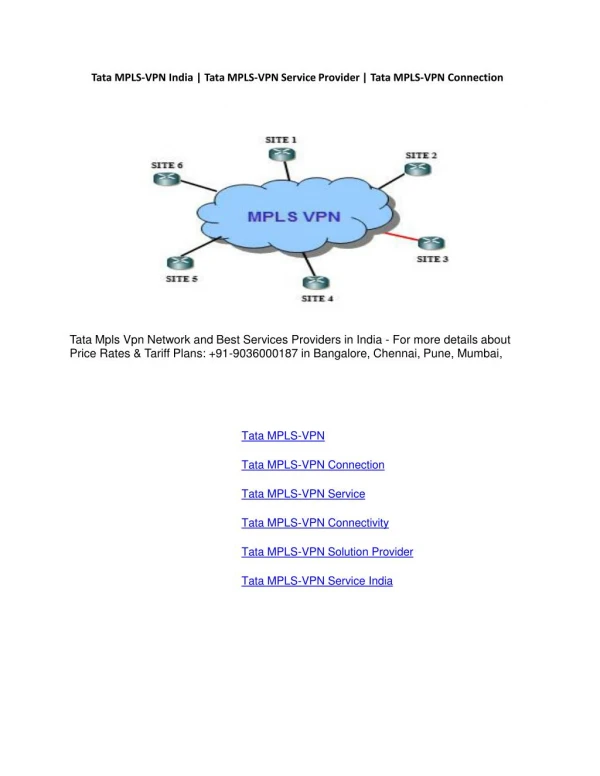
Intranet Corporate Headquarters Branch Office Shared Infrastructure Mobile Users and Telecommuters Remote Access Suppliers, Partners and Customers Extranet What is a VPN? A private network constructed over a shared infrastructure Virtual: not a separate physical network Private: separate addressing and routing Network: a collection of devices that communicate Asghar_Hossy, 11/11/2011
Deploying VPNs in the 1990s Provider Frame Relay or ATM Network DLCI DLCI FR (or ATM)Switch DLCI CPE CPE FR Switch FR Switch • Operational model • PVCs overlay the shared infrastructure (ATM/Frame Relay) • Routing occurs at customer premise • Benefits • Mature technologies • Relatively “secure” • Service commitments (bandwidth, availability, and more) • Limitations • Scalability, provisioning and management problems • Not a fully integrated IP solution Asghar_Hossy, 11/11/2011
VPN Taxonomy • Overlay VPNs—Service providers provide virtual point-to-point links • Peer-to-peer VPNs—Service providers participate in the customer routing Asghar_Hossy, 11/11/2011
Overlay VPNs • Layer 1 Overlay VPN E1/T1, ISDN or SDH/SONET. Mentioned for historical reasons only • Layer 2 Overlay VPN • Traditional switched WAN • Implemented with X.25, Frame Relay, and ATM • SP is responsible for transport of Layer 2 frames • Customer is responsible for all higher layers • Layer 3 Overlay VPN • SP network is invisible to customer routers • Uses IP tunneling • SP provides Point-to-Point data transport between customer sites Asghar_Hossy, 11/11/2011
Virtual Circuit Layer-3 Routing Adjacency CPE (CE) Device CPE (CE) Device Provider Edge (PE) device Provider Edge (PE) device VPN Site VPN Site Service Provider Network VPN - Overlay Model • Private Lines Across a Telco/SP Shared Infrastructure • Leased/Dialup Lines • FR/ATM /X.25 Virtual Circuits • IP(GRE) Tunnelling • Point-to-point Solution between Customer Sites • How to Size Inter-site Circuit Capacities? • Full Mesh Requirement for Optimal Routing • CPE Routing Adjacencies between Sites Asghar_Hossy, 11/11/2011
VPN - Peer-to-Peer Model Layer-3 Routing Adjacencies CPE Router CPE Router Provider Edge Router Provider Edge Router VPN Site 1 VPN Site 2 Service Provider Network • Provider Edge Device Exchanges Routing Information with CPE • All customer routes carried within SP IGP • Simple routing scheme for VPN customer • Routing between sites is optimal • Provisioning (Circuit sizing) no longer an issue • Supports for multiple Overlapping Private Addressing • Addition of New Sites is Simpler • No overlay mesh to concern with Asghar_Hossy, 11/11/2011
VPN Protocols • VPN Remote Access Protocols • PPTP(Point -to -Point Tunneling Protocol) • L2F(Layer 2 Forwarding) • L2TP( Layer 2 Tunneling Protocol) • VPN Site-to-Site Protocols • IPSec (different modes with different level of security) • GRE – Not secure. Mainly used to tunnel other protocols • MPLS VPN Asghar_Hossy, 11/11/2011
Definition/Features of MPLS • Multi-protocol Label Switching • A technology for speeding up network traffic flow and making it manageable • Works by attaching a label in front of each packet • At each subsequent hop in the network, the router only takes a look at the label and forwards it • This is in contrast to the normal switching where routers look at the IP address of each packet and forward it accordingly • This is how MPLS saves time and make traffic flow faster and smoother • Label Distribution: Each LSR in the network maintains a table of {incoming interface, label} and {outgoing interface, label} Asghar_Hossy, 11/11/2011
Circuit Abstraction: Label Swapping D A 2 1 Tag Out New 3 A 2 D • Label-switched paths (LSPs): Paths are “named” by the label at the path’s entry point • At each hop, label determines: • Outgoing interface • New label to attach • Label Distribution Protocol (LDP): responsible for disseminating signaling information Asghar_Hossy, 11/11/2011
VPN - MPLS VPN Model Static, RIP, OSPF, or eBGP Routing Customer Edge (CE) Router Customer Edge (CE) Router Provider Edge (PE) Router Provider Edge (PE) Router VPN Site 1 VPN Site 2 Service Provider Network MP-iBGP Session • Combines Benefits of Overlay and Peer-to-peer Paradigms • Overlay (security and isolation amongst customers) • Peer-to-peer (simplified customer routing) • PE Routers only Hold Routes for Attached VPNs • Reduces size of PE routing information • Proportional to number of VPNs attached • MPLS Used to Forward Packets • Full routing within backbone no longer required • Customers can use overlapping addresses • PE routers participate in customer routing, guaranteeing optimum routing between sites and easy provisioning. Asghar_Hossy, 11/11/2011
Layer 3 VPNs Traditional Layer 3 VPNs: All Customer routes in the core customer routes in the core Site 2 Site 1 CORE IBGP EBGP BGP/MPLS VPNs: BGP between PEs; MPLS in the core LDP LDP LDP Site 1 Site 2 P MPLS CORE P PE PE Asghar_Hossy, 11/11/2011
VPN A/Site 2 10.2/16 VPN B/Site 1 10.2/16 CEA2 CE1B1 10.1/16 CEB2 VPN B/Site 2 P1 PE2 CE2B1 P2 PE1 PE3 CEA3 CEA1 P3 10.3/16 CEB3 10.1/16 VPN A/Site 3 10.4/16 VPN A/Site 1 VPN B/Site 3 Layer 3 BGP/MPLS VPNs BGP to exchange routes MPLS to forward traffic • Isolation: Multiple logical networks over a single, shared physical infrastructure • Tunneling:Keeping routes out of the core Asghar_Hossy, 11/11/2011
BGP/MPLS VPN key components • Forwarding in the core:MPLS • Distributing routes between PEs:BGP • Isolation:Keeping different VPNs from routing traffic over one another • Constrained distribution of routing information • Multiple virtual forwarding tables • Unique addresses: VPN-IP4 Address extension • Overlapping IP Addresses Asghar_Hossy, 11/11/2011
Problems Introduced by Layer 3 VPNs • Overlapping address space in forwarding table • Solution:Virtual routing and forwarding table (“VRF”) • Overlapping address space in BGP routes • Solution:“Route distinguisher”--- 8-byte VPN-specific identifier prepended to each IP address • Typically, one route distinguisher per VPN • New VPN-IP address family • Routes carried with Multi-Protocol BGP (MP-BGP) • Filtering routes from routes not at that site • Route target: basically a special BGP community value Asghar_Hossy, 11/11/2011
Route Distinguisher Asghar_Hossy, 11/11/2011
Route Distinguisher (Contd.) • VPNv4 addresses are exchanged between PE routers via BGP • BGP that supports address families other than IPv4 addresses is called Multiprotocol BGP (MPBGP) Asghar_Hossy, 11/11/2011
Site 3 Site 1 Site 2 Site 5 VPN 2 VPN 3 VPN 1 Site 4 Route Targets • Think of this as a VPN Id • Some sites participate in more than one VPN • The RD cannot identify participation in more than one VPN • RTs were introduced in the MPLS VPN architecture to support complex VPN topologies and multiple sites • RTs are additional attributes that attach to VPNv4 BGP routes to indicate VPN membership Asghar_Hossy, 11/11/2011
Virtual Routing and Forwarding • Separate tables per customer at each router Customer One 10.0.1.0/24RD: 999:1 10.0.1.0/24 Customer One Customer Two 10.0.1.0/24 Customer Two 10.0.1.0/24RD: 999:2 Asghar_Hossy, 11/11/2011
Site 2 Site 1 Site 3 Routing: Constraining Distribution • Performed by Service Provider using route filtering based on BGP Extended Community attribute • BGP Community is attached by ingress PE route filtering based on BGP Community is performed by egress PE Static route, RIP, OSPF or EBGP BGP RD:10.0.1.0/24Route target: 65999:1Next-hop: A A 10.0.1.0/24 Asghar_Hossy, 11/11/2011
Forwarding • PE and P routers have BGP next-hop reachability through the backbone IGP • Labels are distributed through LDP (hop-by-hop) corresponding to BGP Next-Hops • Two-Label Stack is used for packet forwarding • Top label indicates Next-Hop (interior label) • Second level label indicates outgoing interface or VRF (exterior label) Corresponds to LSP of BGP next-hop (PE)o LSP ofBGP next-hop (PE) Corresponds to VRF / interface at exit Layer 2 Header Label1 Label Label2 IP Datagram IP Datagram
Forwarding in BGP/MPLS VPNs • Step 1: Packet arrives at incoming interface • Site VRF determines BGP next-hop and Label #2 Label2 IP Datagram • Step 2: BGP next-hop lookup, add corresponding LSP (also at site VRF) IP Datagram Label1 Label2 Asghar_Hossy, 11/11/2011
MPLS VPN Lab Asghar_Hossy, 11/11/2011
Conclusion • VPNs allow you to use the shared infrastructure of a SP to implement your private networks. There are two implementation models: overlay and peer-to-peer. • Virtual Private Networks provide the highly desirable benefits of low-cost, high speed, and secure connection • MPLS, on the other hand, provide better Quality of Service based on Traffic Engineering and Resource Reservation • The MPLS VPN architecture offers SPs a peer-to-peer VPN architecture that combines the best features of overlay VPNs with the best features of peer-to-peer VPNs. • MPLS VPNs use a 64-bit prefix called the route distinguisher (RD) to convert non-unique 32-bit customer IPv4 addresses into 96-bit unique addresses that can be transported. • MPLS works by prepending packets with an MPLS header, containing one or more “labels.” This is called a label stack. Asghar_Hossy, 11/11/2011
Thank You Everybody. Asghar_Hossy, 11/11/2011