Download
1 / 73
750 likes | 1.12k Views
Planned GPS Civil Signals and Their Benefits to the Civil Community Dr. A. J. Van Dierendonck AJ Systems. Acknowledgements. Briefing taken from Chris Hegarty’s Navtech Course to be given at ION-GPS-2001 But then, he is using a lot of my charts

E N D
Planned GPS Civil Signals and Their Benefits to the Civil CommunityDr. A. J. Van DierendonckAJ Systems
Acknowledgements • Briefing taken from Chris Hegarty’s Navtech Course to be given at ION-GPS-2001 • But then, he is using a lot of my charts • Briefing includes Tom Stansell’s charts on L2CS signal • Briefing includes some Navstar JPO charts
Presentation Topics • GPS Modernization Overview • New Civil Signals Detail • Performance Enhancements
GPS Modernization Overview • Why modernize? • GPS modernization plans • New civil signal summary • Galileo compatibility; plans
Why Modernize? • National policy - GPS is a vital dual-use system • For civil users, new signals/frequencies provide: • More robustness against interference, compensation for ionospheric delays and wide/tri-laning • For military users, new signals provide: • Enhanced ability to deny hostile GPS use, greater military anti-jam capability and greater security • For both civil/military, system improvements in accuracy, reliability, integrity, and availability
March 1996 Presidential Decision Directive (PDD) • GPS is free for peaceful use worldwide • GPS is dual civil/military system • Selective Availability (SA) to be discontinued by 2006 (occurred in 2000) • GPS and U.S. augmentations to be managed by Interagency GPS Executive Board (IGEB)
Civil GPS Modernization - National Policy • February 1997 - DoD and DOT agree to provide a 2nd civil GPS frequency • March 1998 - IGEB decision to implement two new civil signals • January 1999 – 3rd civil signal frequency announced - 1176.45 MHz • February 1999 - IGEB formed 3rd Civil Signal Implementation Steering Group • Established relationship between IGEB and RTCA for development of L5 signal requirements
Civil Modernization - National Policy (continued) • November 1999 - IGEB report Implementation of a Third Civil GPS Signal completed • Recommended implementing L5 with: • 6 dB higher minimum received signal power than L1 C/A code • 10.23 Mchip/second spreading codes on quadrature channels (no data on one channel) • Other recommendations regarding coexistence of L5 with existing systems operating at/near 1176.45 MHz • Link 16 • Distance Measuring Equipment (DME)/Tactical Air Navigation (TACAN)
Modernized Signal Evolution L5 L2 L1 C/A P(Y) P(Y) Present Signals CS C/A M M Signals After Modernization P(Y) P(Y) 1176 MHz 1227 MHz 1575 MHz
L5 - New Civil Signal • Safety-of-life use • Higher accuracy to users when used with C/A on L1 • Similar accuracy as military service today • Much more robust compared with C/A on L1 • Greater resistance to interference • Approximately four times more power • Improved data message • Higher chipping rate improves multipath performance • Located in an Aeronautical Radio Navigation Service (ARNS) band for safety-of-life services use (e.g., civil aviation) 1176.45 MHz
L2 Civil Signal (L2CS) • More robust civil signal service • Civil users currently only have codeless/ semi-codeless access to P(Y) on L2 • Increased accuracy • Coded dual-frequency ionospheric corrections at the receiver in the clear • Preferred option - advanced signal structure • Better cross-correlation properties than C/A • Data-free component for robust tracking
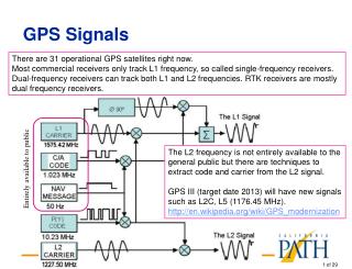
New GPS Signals - Summary • Today - 2 navigation frequencies, 3 signals • L1 = 1575.42 MHz (154 × 10.23 MHz) • Coarse Acquisition (C/A) code • Precision P(Y) code • L2 = 1227.6 MHz (120 × 10.23 MHz) • P(Y) code • Near future - 3 navigation frequencies, 7 signals • L1 C/A, P(Y), and M-code • L2 CS, P(Y), and M-code • L5 = 1176.45 MHz (115 × 10.23 MHz)
GPS Spreading Codes Signal Chipping Rate Carrier frequency Comments (Mchip/s) (MHz) C/A 1.023 1575.42 (L1) 1023-chip Gold codes repeat every ms CS 1.023 1227.6 (L2) 2 codes per SV each at 511.5 kHz, future P(Y) 10.23 L1 and L2 Repeats once/week L5 10.23 1176.45 (L5) 2 codes per SV, future M 5.115 L1 and L2 code modulated by 10.23 MHz square wave, future
Signal Power Spectra -6 x 10 1 C/A or L2CS 0.8 0.6 Normalized Power Spectrum (W/Hz) 0.4 M P(Y) 0.2 0 -15 -10 -5 0 5 10 15 Offset from Carrier Frequency (MHz) Notes: (1) C/A codes actually have line spectra - continuous approximation shown. (2) L5 signal spectrum resembles P(Y), except that L5 is also a line spectrum.
GPS Modernization Program • Last 12 Block IIRs • Add second civil signal (L2CS) and new military signal (M-code) - more signal power • First 6 Block IIFs (“IIF Lite”) • All of above plus new 3rd civil signal (L5) • Next (nominally) 6 Block IIFs • Procured as necessary to sustain the constellation • GPS III (Full Modernization) • Meet future requirements through 2030 - more M-code signal power • Operational Control Segment (OCS) • Evolutionary incremental development
Block IIR- Modified Satellites • L2 Enhancements • New L2CS at -160 dBW • New ME code at -158 dBW • L1 Enhancement • New ME code at -158 dBW L1 L2 - Two new military signals - One new civil signal - No changes required to batteries or solar arrays
Block IIF Satellites • L2 Enhancements • New ME code added • C/A code on L2 L2 • L1 Enhancements • New ME code added L1 L5 • L5 Signal • New robust Civil Signal • Power level = -154 dBw • Two new military signals • One new civilian signal (C/A on L2 already present) • Could increase power on some of these signals
FIX FOM 1 N 42* 01” 46.12” W 091* 38’ 54.36” EL + 00862 ft 3 menu 1 ON 2 4 5 6 7 WPT 8 POS 9 NAV CLR MARK 0 OFF NUM LOCK ZEROIZE Rockwell GPS III Overview The GPS III System Maintain Space User Service Second Civil Signal M-Code Third Civil Signal • Relook at entire GPS Architecture to: • Achieve long term GPS performance goals • Limit long-term total ownership costs • Ensure GPS system properly addresses and is synergized with • Military and Civil Needs/Systems • Possible augmentation opportunities • Ensure best GPS system for the nation for the next 30 years
1999 2000 2001 2002 2003 2004 2005 2006 2007 2008 2009 2010 2011 2012 2013 2014 2015 2016 2016 SPI Contract Definitization GPS Modernization Integrated Schedule CY 2017 Milestones M-Code Earth (24 SV) M-Code Earth (18SV) IIR Mod First Launch GPS-III Full Capability IOC GPS-III Full Capability FOC L5 IOC L5 FOC IIF SV1 Launch ATP IIR SV10-SV21 IIR Mod Deliveries IIR SV10-SV21 IIR Mod Launches Space Segment IIF SV1-SV6 IIF SV7-SV12 IIF Lite Deliveries IIF SV1-SV6 IIF SV7-SV12 IIF Lite Launches SV1-SV3 SV4 - SVNN GPS III Deliveries SV1-SV3 SV4 - SVNN GPS III Launches Control Segment M-Code/L5 OCS IIF OCS Deliver S/W OCS Training/Validation OT&E Comp.
GPS Constellation Size • Through Block IIF modernization, GPS will remain a nominally 24 satellite constellation • GPS III architecture studies are considering larger constellations as part of system-level trades • Performance benefits of larger constellation • Backward compatibility and costs are two difficulties
Galileo Compatibility/Plans • U.S. and European Union engaged in high-level talks on GNSS cooperation • U.S. delegation led by State Department • Low-level discussions will follow establishment of principles for cooperation • Lots of less formal discussions in various forums (e.g., International Civil Aviation Organization GNSS Panel, Joint Program Office visits) • Key issue: should GPS, Galileo share spectrum?
New Civil Signals • L5 • Signal structure and pseudorandom noise (PRN) codes • Navigation message and data format • Spectrum issues • L2CS • Signal structure and PRN codes • Implementation options
L5 Signal Specification • IGEB Working Group 2 (WG2) chartered to develop L5 Signal Specification • Formal relationship established with RTCA Special Committee 159 (SC159) WG1 • December 2000 - RTCA recommendations published (RTCA DO-261) • Air Force has converted RTCA document into L5 Interface Control Document (ICD-GPS-705)
L5 Characteristics Summary • L5 = 1176.45 MHz • Bandwidth = 24 MHz (filed) • Minimum Received Power = -154 dBW • PN Code Chipping Rate = 10.23 MHz • QPSK Signal • In-Phase (I) = Data Channel • Quadraphase (Q) = Data-Free Channel • Equal Power in I and Q (-157 dBW) • Independent PRN Codes on I and Q
L5 Characteristics Summary (cont’d) • I and Q Modulation (1 kbps) • Forward Error Correction (FEC) encoded 50 bps data on I (100 sps) • Further encoded with 10-bit Neuman-Hoffman Code • Q encoded with 20-bit Neuman-Hoffman Code • More details to follow
Data-Free Channel • No data on Q-channel allows coherent carrier/code tracking • Allows tracking in lower SNR conditions • Power stolen from data recovered through use of forward error correction (FEC)
Optimum Division of Power Between Data and Dataless Channel Courtesy of Dr. Tom Morrissey, Zeta Associates
L5 Codes • Codes with 2 - 13 stage shift registers • Length of one (XA code) = 8190 chips • Length of second (XB code) = 8191 chips • Exclusive-Or’d together to generate longer code • Chipping rate of 10.23 MHz • Reset with 1 ms epochs (10,230 chips) • Two codes per satellite (4096 available) • One for Data channel, one for Data-Free channel
Baseline Codes’ Properties • Same multipath/noise accuracy as P code • Narrowband and CW interference rejection is much better than the GPS C/A code • Not quite as good as P code • Coupled with encoded data bits • Wideband noise rejection is same as P code • Direct acquisition capability • Not practicably available using P code
Probability of Cross-Correlation Level - 0 to 5 kHz C/A Codes L5 Codes
L5 Power Spectral Density - Reduces the Effect of CW Interference
L5 Code Performance Summary • 74 Codes have been selected • 37 I, Q pairs • Max non-peak autocorrelation -30 dB • Maximum cross-correlation with other selected codes -27 dB • Maximum cross-correlation between I, Q pairs < -74.2 dB • Another pair selected as non-standard code
L5 I and Q Code and Symbol Modulation • (Coded) coherent carrier in-quadrature with data • Allows for robust code & carrier tracking with narrow pre-detection bandwidth • Independent codes to remove QPSK tracking bias
L5 Neuman-Hoffman Codes • Encoded symbols and carrier • Modulate at PRN Code epoch rate • Spreads PRN Code 1 kHz spectral lines to 50 Hz spectral lines (including FEC) • Reduces effect of narrowband interference by 13 dB • Primary purpose of NH Codes • Also allows detection of narrowband interference • Reduces SV cross-correlation most of the time • Provides more robust symbol/bit synchronization
Typical Spectral Sidelobes Including 10-Bit Neuman-Hoffman Code • 20-Bit Code on Q-Channel reduces spectrum another 3 dB
L5 Data Content and Format • 5 – Six-Second 300-bit Messages • Format with 24-bit cyclic redundancy code (CRC) (same as WAAS) • Encoded with Rate 1/2 FEC • To make up for 3-dB QPSK reduction • Symbols modulated with 10-bit Neuman-Hoffman Code • Messages scheduled for good performance • Lined up with L1 sub-frame epochs
L5 Message Types (of 64 possible) • Message Type 1 - Ephemeris/Clock I • Message Type 2 - Ephemeris/Clock II • Message Type 3 - Ionosphere/UTC • Message Type 4 - Almanac • Message Type 5 - Text Message • Anticipated that Ephemeris/Clock Messages would be repeated every 18-24 seconds
Message Content • Mostly, content is same as on L1 • Clock parameters describe L1-C/A/L5 combined offset rather than L1-P/L2-P combined offset • L1/L5 Group Delay variable for single frequency users • Add L5 Health • Different Text Message • Add PRN number • Peculiar L5 information can be provided by civil community
L5 Interference Environment - Primary Concerns • DME/TACAN • Over 1700 U.S. ground beacons • 1 MHz channels across 960-1215 MHz • EIRP = 100 W - 10000 W • 3.5 ms pulse width (1/2 voltage) • 2700 - 3600 pulse pairs/s • JTIDS/MIDS • Now 600 terminals (many airborne) • May be 4000 U.S. terminals by 2010 • Hops over 51 3 MHz channels from 969-1206 MHz • 6.4 ms pulse width • For uncoordinated exercises: • Peak power = 200 W • 396,288 pulses/12 s in 200 nmi radius
L5 Receiver Requirements • Primary contributors to electromagnetic environment near L5 are pulsed • More selective front-end (compared to L1 avionics) necessary to limit number of pulses desensitizing receiver • “Pulse blanking” a low-cost, low-risk method to minimize effects on receiver performance • Performance standards should not specify design, but will require operation in pulsed environment
Example of Worst-Case DME/TACAN Environment in U.S. Victim aircraft at 40,000 ft over Harrisburg Note: Only TACAN/DMEs with frequency assignments from 1157 - 1209 MHz are shown/analyzed.
SNR Degradation at 40,000 ft - All Known U.S. Emitters with Reassignment of In-band DME/TACANs