Download

1 / 34
340 likes | 359 Views
Learn about communal heating systems & design criteria. Understand peak load calculation & system design for efficiency.

E N D
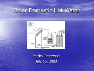
Design of Heating and Hot Water Interface Units for Properties Connected to Communal Heating Systems
What is a Communal Heating System? • Heating and hot water are supplied from a centralised plant room rather than from separate boilers within each dwelling. • Dwellings can either be individual low rise properties or more usually, medium to high rise apartment blocks. • Heat energy is supplied into each dwelling via an interface unit which gives independent control over heating and hot water for each residence. • The interface unit usually contains an energy meter to enable charging for the energy consumed.
Why use a Communal Heating System? • Can help achieve compliance with Planning, Building Control and Sustainability Code Requirements. • Allows the use of waste heat from local industry or geothermal energy source. • Can integrate a mixture of heat sources – fossil fuel, biomass and combined heat and power. • Allows a contribution from renewable energy sources – solar thermal, air source or ground source heat pumps. • No need for a flue or gas supply in each dwelling.
System Design Criteria – Central Plant • Primary Heat Source - Oil, Gas, Biomass, Combined Heat and Power, Heat Pump or Other off site source. • Need to calculate the peak load requirement • Need flexibility to cover breakdown or periods of planned maintenance – duplicate systems? • Ability to cope with variable load • Buffering requirements - size of buffer store? • Boiler flow and return – is there a requirement for low return temperatures?
Peak Load Calculation Need to establish the hot water and heating load requirements for each apartment. These values are then scaled up by the number of apartments and multiplied by a Coincidence Factor to give the peak load and distribution pipe diameters for the whole building. The Coincidence Factor is a statistical estimation of the simultaneous peak loading within a building and is usually expressed as a value of less than one dependent on the number of dwellings attached to the system. The two standards which are most commonly referred to are the Danish DS439 and British BS6700.
Peak Load Calculation It is evident that there is a considerable disagreement between the two standards. In reality we are trying to calculate the amount of energy which must be available within the distribution system to meet the actual simultaneous peak demand. Clearly with just one apartment the factor is 1 (or 100%), but as the number of apartments increases then the statistical factor value decreases. For example if we have 80 apartments on the system then the BS standard requires 25% of the maximum load, but the Danish standard requires only 10%. Which one is correct?
Peak Load Calculation We need to consider the building as a whole for calculating peak boiler load from the central plant room, but we must also consider each block and landing as a separate entity for pipe sizing. Statistically, a landing of only 4 apartments would require a Coincidence factor of between 0.35 and 0.55 depending on which standard is being used. In reality the actual peak load depends on: • Number of tap outlets • Flow rate and temperature of each outlet • Number of occupants • Social status of the development • Apartment occupancy utilisation
An Example Peak Load Calculation for a 3 bed apartment with family bathroom and ensuite shower, with 4 occupants Waterload Calculator is set up to provide a bath, shower and 2 wash basins within a time frame of 10 minutes.
Maximum Power Requirements (kW) For this example, the calculation shows that a peak load of 80kW is required to achieve the desired Domestic Hot Water output.
Peak Load Calculation for whole building using the Danish Standard Coincidence Factor Example: a small block of apartments comprising 4 floors with 4 x three bed apartments on each floor. Peak load for each apartment = 80kW dhw + 6kW htg = 86 kW Peak load for each floor using a coincidence factor of 0.35 = (80 x 4 x 0.35) + (4 x 6) kW = 136 kW Peak load for whole building using a coincidence factor of 0.2 = (80 x 16 x 0.2) + (16 x 6) kW = 352 kW
System Design Criteria – Distribution • Distribution System – Peak load determines the size of pipes, pumps and valves • Allocation of space in apartments for HIU • Differential pressure regulation • Overheating in common areas through heat losses from distribution pipework • Capital Costs – Central Plant room • Capital Costs – Distribution pipework • Capital Costs – HIU in each apartment • Maintenance Costs – Servicing and Response to system failure • Metering and Billing Systems
Heat Interface Units We will now look more closely at four different types of heat interface unit: • Single Interface plate heat exchanger for DHW with Central Heating directly from the primary supply • Double Interface using two plate heat exchangers, one for DHW and one for Central Heating • Single Interface plate heat exchanger with ‘S’ plan control for Central Heating and unvented hot water storage cylinder with coil recovery, for DHW • Single Interface plate heat exchanger to thermal store which in turn provides DHW and central heating
Single Interface PHE for DHW, CH direct from primary • No Isolation between systems • High peak loading for DHW • Require quick response from primary system for DHW • Possible high ambient temperatures from distribution losses • No electric back up for heating or DHW
Double Interface using two PHEs one for DHW, one for CH • Isolation between systems • High peak loading for DHW • Require quick response from primary system for DHW • Possible high ambient temperatures from distribution losses • No electric back up for heating or DHW • Require pressure relief discharge from heating
Single Interface PHE with ‘S’ plan control for CH and Unvented hot water storage cylinder with coil recovery for DHW • Isolation between systems • High peak loading for DHW met using storage • Averaged demand from primary system for DHW • Primary pipework can go cold (no demand) • Electric backup for hot water • No electric back up for heating • Pressure relief discharge from heating • Unvented storage safety discharges • Must heat up full store in one go
Single Interface PHE to Thermal Store • Isolation between systems • High peak loading for DHW met using storage • Averaged demand from primary system for DHW • Primary pipework can go cold (no demand) • Electric back up for hot water and heating • Control over amount of DHW stored • No discharges from property • Store must be at high point if discharges are to be avoided
Peak Load Calculation with 6 kW boiler input Waterload Calculator is set up to provide a bath, shower and 2 wash basins within a time frame of 10 minutes and 6 kW boiler input
Load Calculations showing HIU Storage Volume and Recovery Time for 6 kW input Output also shows that 134 litres minimum storage required. Typically 45 litres added for central heating. (=180 litres)
Without and With Storage 80 kW HW
The Advantages of Distributed Storage • Using stores in properties adds considerable volume of total storage to the system. 100 properties = 10,000 to 20,000 litres. • Allows higher hot water flow rate in each property • Averages out the energy demands from the central plant, can reduce total boiler capacity. • Reduces distribution pipe sizing. • Allows distribution pipework to go cold during periods of low or no demand, without affecting hot water function in properties. This results in reduced heat losses to the fabric and prevents hallways from overheating in summer. • Reduced plant room size, without the need for large buffer storage vessels. • Provides for electric backup in properties. • Allows intelligent load balancing on CHP Plants.
Thermal Storage – The Pandora Unit • Can overcome discharge requirements, providing central heating is on (or below) same level as store. • Provides for electric (and multi-fuel) backup of central heating in properties, as well as hot water. • Allows selection between electric/heat for central heating, as well as hot water. • Legionella protection easier to accomplish without stored DHW.
Thermal Store with Plate Heat Exchanger Recovery • Plate Heat Exchanger recovers the cylinder from the top down which provides rapid availability of Hot Water from a cold start. • Allows control over amount of storage to be heated. Economy mode during summer, full store for heating during winter • DHW priority – the take off point for dhw is higher up the cylinder. • Return temperatures to plant can be effectively controlled. • When required can recover cylinder at very high transfer rates (up to 80 kW) distribution system permitting.
Why use an External Plate Heat Exchanger rather than Internal Coil?
Pandora Heat Bank Thermostat
Pre-Fabricated Heat Bank Thermal Store Pre-fabricated Pandora Heat Bank thermal stores provide for both storage and heat exchanger systems, along with all the appropriate controls. Differential Pressure Regulation. Complete Heat Metering and Billing Solution.
Heatweb Design Tools for Communal Interfaces www.heatweb.com
Energy Metering The interface units are supplied with an energy meter which monitors and records the energy consumed within each dwelling. The energy meter is only one component of a total metering solution which has to provide for: • Tariff Calculation – the unit cost of energy, taking into account fuel, servicing and maintenance • Customer Service Charge – meter data collection, bill calculation and preparation, revenue and debt collection • System Monitoring – need to optimise boiler efficiency, operating costs, tariff adjustment, checking for fraud
Metering Options Selecting the most suitable metering solution for each project will require extensive client involvement. Some solutions have low capital cost but high service charges which are ultimately passed on to residents whereas others have high capital cost but low services charges. It is essential that the client makes a decision at an early stage as to which billing solution they want to proceed with, and whether they want to carry out revenue collection in house or via a third party.
Metering Solutions The following options tend to be low capital cost but can attract high service charges: • Manual readings from read only meters • Manual readings from hand held wireless reader • Remote readings via an MBUS data cable to an on site office, or using GSM, land line or internet modem to an off site location In all of the above options data is collected, bills are prepared and submitted for revenue collection in arrears. MBUS data collection also allows plant monitoring and optimisation.
Metering with Smart Options The energy meter can be connected to a card reader which enables various types of prepayment systems to be used: • Preloaded pay as you go cards which are purchased from a management office or local store • Prepayment cards which can be topped up by management software through local pay stations • Smart cards which offer a variety of top up methods from pay stations to by direct debit via the internet. It is usual for prepayment options to provide an emergency credit extension for when top up may be unavailable. Very often the building is a mixture of private ownership and rented requiring more than one billing solution to be used.
Thank you for your attention • Please help yourself to leaflets. • I will be pleased to demonstrate the heatweb design tools if anyone would like to see them in more detail. CPD written by: Richard Hanson-Graville, Technical Manager, Thermal Integration Ltd. Richard Baker, Commercial Sales, Specflue Ltd.