Load sharing in PBB-TE
Load sharing in PBB-TE. Zehavit Alon IEEE Interim Meeting May 2008. Definitions. BSI - Backbone service instance (identified by I-SID) TESI – TE service instance (identified by TE-SID which corresponds to a series of 3-tuples <ESP-MAC DA, ESP-MAC SA, ESP-VID> TEPG – TE Protection Group

Load sharing in PBB-TE
E N D
Presentation Transcript
Load sharing in PBB-TE Zehavit Alon IEEE Interim Meeting May 2008
Definitions • BSI - Backbone service instance (identified by I-SID) • TESI – TE service instance (identified by TE-SID which corresponds to a series of 3-tuples <ESP-MAC DA, ESP-MAC SA, ESP-VID> • TEPG – TE Protection Group • Preferred TESI - A configuration option that specifies the preferred path for a BSI • Alternate TESI - A configuration option that specifies the alternate path for a BSI in the event of a failure of its preferred TESI • Protection switching - Quote from the introduction of G.8031 - “Protection switching is a fully allocated survivability mechanism. It is fully allocated in the sense that the route and bandwidth of the protection entity is reserved for a selected working entity. It provides a fast and simple survivability mechanism.”
Protection Switching Models 1:1 w/o load sharing N×(M:1) with load sharing The TEPG is composed of 2 TESIs. The TEPG is composedof N TESIs. (N > 1, M < N-1) One TESI in the TEPG is defined as the working TESI and the other is defined as the protection TESI. One of the N TESIs in a TEPG can serve as the preferred TESI for a BSI and one of the remaining (N-1) TESIs can serve as the alternate TESI for that BSI. Each BSI in a TESI is protected against a single failure by the other TESI that belongs to the TEPG. Each BSI in a TESI is protected against a single failure by one of the other N-1 TESIs that belong tothe TEPG. All the BSIs in the TEPG are carried by one of the TESIs in the TEPG. BSIs are carried by different TESIs that belong to the TEPG. When the working TESI fails, all the BSIs that are carried by it are switched to the protecting TESI. When a TESI fails, each BSI that is carried by it is switched to one of the remaining TESIs (its alternate TESI).
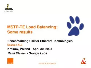
Each BSI is mapped to the TEPG 4 TESIs 2 TEPG 12 BSI I-LAN 1:1 without load sharing
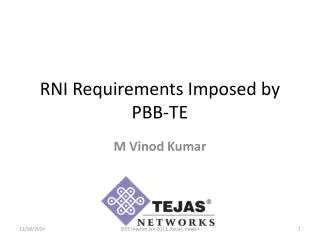
Each BSI is mapped to the TEPG and is configured with the preferred and alternate TESIs 4 TESIs 1 TEPG 12 BSIs I-LAN N×(M:1)with load sharing Each BSIs from the failed TESI is moved to a different TESI
Comparison between the 2 modelsManagement and Operation Manual Switch to working Manual Switch back of BSI Manual Switch back of BSI Manual Switch back of BSI I-LAN I-LAN Manual Switch of TESI Manual Switch to protection
Comparison between the 2 models Management and Operation (cont’d)
70% 100% 100% 100% Comparison between the 2 modelsResource utilization I-LAN No Available BW in the alternate TESI
Comparison between the 2 modelsSignaling (future functionality)
Comparison between the 2 modelsGeneral 50G 50G 50G 50G
Motivation for load sharing • BW saving BUT To provide protection switching, each BSI must have a pre-provisioned backup path. To provide protection for X BW, prior allocation of 2X BW is required as in 1:1 protection switching. • Good utilization of network resources BUT The assignment of BSIs to TESIs is static rather than dynamic and is configured in the same way as for 1:1 protection switching. • Better utilization of network resources and links BUT The same functionality can be achieved in both modes. • Define 4 TESIs of 50G BW consisting of 2 TEPGs, instead of 1 TEPG with 2 TESIs of 100G each • Distribute traffic between links (instead of LAG) by sharing the TEPGs among the links instead of distributing the TESIs of a single TEPG
Conclusions • The N×(M:1) path protection with load sharing model • Does not add any useful functionality that cannot be easily achieved using the 1:1 model • Adds complexity to management and operation • Adds complexity to calculate the resources needed for each TESI in a TEPG to guarantee protection • Will be difficult to synchronize between the edges • Adds complexity in the bridge’s internal implementation • Not in the scope of PAR • The draft covers 2 solutions with completely different mechanisms, different state machines, different capabilities, and different methods of operation for the 1:1 and N×(M:1) models. Therefore, it does not comply with the PAR that states: “1:1 path protection switching capable of load sharing”.
Recommendation • Comply with the scope of the PAR by including 1:1 path protection switching only, providing the load sharing capability by means of the 1:1 path protection mechanism • Remove support for the N×(M:1) load sharing model from the current project
Thank You zehavit.alon@nsn.com
Protection Switching • Protection switching is defined as guarantied if the resources needed to carry traffic of failed resource are pre-alocated. I.e. each TESI must have enough BW to carry all the BSI that are mapped to it (preferred and alternate) • The assumption that N×(M:1) load sharing will save bandwidth is incorrect since all the traffic of a failed TESI must have a protection path. Similarly, the assumption that only a single TESI of a protection group may fail is incorrect. • N×(M:1) load sharing can be achieved by defining several 1:1 TESIs with load sharing. Operating such a system is straightforward. • Since assigning a BSI to a TESI is static rather than dynamic, traffic characteristics at a given moment (heavy or moderate) do not influence this operation.
Manual switch • Force switch, as defined in 26.10.5.1.3 : “A Boolean flag associated with a particular TESI indicating the presence of an administrative command to make this TE service instance available while all the other TE service instances in the protection group (12.19.1.2.2) unavailable. Its value is controlled by an administrator action (12.19.2.1.3:e6)” • In this case, each TESI must be able to carry all traffic from all the other TESIs, i.e NX, in contrary to what is explained in annex M that claims that “Using conventional 1:1 protection the bandwidth reserved for protection is 100% of the working bandwidth. Using 1:1 protection with load sharing the bandwidth reserved for protection can be significantly reduced” • On the other hand, if the command is as defined in http://www.ieee802.org/1/files/public/docs2008/ay-mack-crane-load-sharing-protection-0308.pdf i.e remove traffic from a selected entity. In order to switch back to the original mapping it is necessary to locate all the switched BSIs and switch each of them back. This cannot be done per TESI since the TESI does not recognize the preferred TESI of each of the BSIs that are in the alternate TESI.
Configuration and Management • The configuration and management of N×(M:1) is much more complicated than 1:1 and includes additional configuration commands. • Assuming we have 12 BSIs and we want to use 4 different paths, we need to configure: • N×(M:1) model • 4 TESIs • 1 protection group • 12 BSI attachments to the protection group • 24 (12 * 2) preferred and alternate TESI selection per BSI • 40 commands • 1:1 model • 8 TESIs • 4 protection groups • 12 BSI attachments to the protection groups • 24 commands • The configuration complexity increases the likelihood of inconsistency between the TESI edges.