Download
1 / 54
540 likes | 593 Views
Learn the direct stiffness method for trusses to efficiently obtain structure stiffness matrices. Follow detailed steps for formation of total structure stiffness matrix using element stiffness and deformation transformation matrices.

E N D
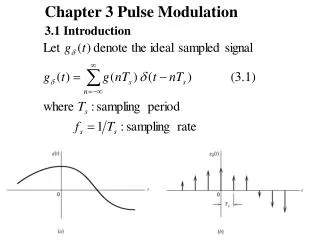
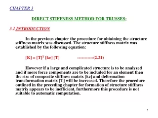
CHAPTER 3 DIRECT STIFFNESS METHOD FOR TRUSSES: 3.1 INTRODUCTION In the previous chapter the procedure for obtaining the structure stiffness matrix was discussed. The structure stiffness matrix was established by the following equation: [K] = [T]T [kc] [T]-----------(2.21) However if a large and complicated structure is to be analyzed and if more force components are to be included for an element then the size of composite stiffness matrix [kc] and deformation transformation matrix [T] will be increased. Therefore the procedure outlined in the preceding chapter for formation of structure stiffness matrix appears to be inefficient, furthermore this procedure is not suitable to automatic computation.
In this chapter an alternative procedure called the “direct stiffness method” is introduced. This procedure provides the basis for most computer programs to analyze structures. In this method each individual element is treated as a structure and structure stiffness matrix is obtained for this element using the relationship: [K]m = [T]Tm[k]m [T]m-----------(3.1) Where [K]m= Structure stiffness matrix of an individual element. [T]m = Deformation Transformation matrix of an individual element. [k]m = Member Stiffness matrix of an individual element. Total structure stiffness matrix can be obtained by superimposing the structure stiffness matrices of the individual elements..
As all members of a truss are not in the same direction i.e. inclination of the longitudinal axes of the elements varies, therefore stiffness matrices are to be transformed from element coordinate system to structure or global coordinate system. When the matrices for all the truss elements have been formed then adding or combining together the stiffness matrices of the individual elements can generate the structure stiffness matrix [K] for the entire structure, because of these considerations two systems of coordinates are required. i) Local or member or element coordinate system: In this coordinate system x-axis is collinear with the longitudinal axis of the element or member. Element stiffness is calculated with respect to this axis. This system is illustrated in figure 3.1
ii) Structure or global coordinate system: A single coordinate system for the entire structure is chosen, with respect to which stiffness of all elements must be written. 3.2 PROCEDURE FOR THE FORMATION OF TOTAL STRUCTURE STIFFNESS MATRIX FOR AN ELEMENT USING DIRECT STIFFNESS METHOD: Following is the procedure for the formation of structure stiffness matrix: i) Formation of the element stiffness matrix using equation 2.16. ----------- (2.16) ii) Formation of the deformation transformation matrix [T] for a single element: []m = [T]m []m -----------(3.2)
where []m = Element or member deformation matrix. []m = Structure deformation matrix of an element or member [T]m = Element or member deformation transformation matrix. (iii) Formation of a structure stiffness matrix [K] or an element using the relation [K]m = [T]Tm[k]m [T]m -----------(3.1) The above mentioned procedure is discussed in detail in the subsequent discussion. 3.2.1 The formation of element stiffness matrix in local co-ordinates: It has already been discussed in the previous chapter. However it is to be noted that for horizontal members the structure stiffness matrix and element stiffness matrix are identical because both member coordinate systems and structure coordinate systems are identical. But for inclined members deformation transformation matrices are to be used because member coordinate system and structure coordinate system are different; therefore their structure stiffness matrix and element stiffness matrix will also be different.
3.2.2 The formation of deformation transformation matrix: As the main difference between the previously discussed method and direct stiffness method is the formation of the deformation transformation matrix. In this article deformation transformation matrix for a single element will be derived. Before the formation of deformation transformation matrix following conventions are to be established in order to identify joints, members, element and structure deformations. 1) The member is assigned a direction. An arrow is written along the member, with its head directed to the far end of the member. 2) i, j, k, and l, are the x and y structure deformations at near and far (tail & head) ends of the member as shown in figure 3.2. These are positive in the right and upward direction. 3) r and s are the element deformations at near and far (tail & head) ends of the member as shown in figure 3.2. 4)The member axis (x-axis of member coordinate system) makes an angle x, with the x-axis of the structure coordinate system as shown in figure 3.2. 5)The member axis (x-axis of member coordinate system) makes an angle y, with the y-axis of the structure co-ordinate system as can be seen from figure 3.2. 6) The cosines of these angles are used in subsequent discussion Letters l and m represent these respectively.
l = Cos qx and m = Cos qy l = Cos qx = m = Cos qy = The algebraic signs of θ‘s will be automatically accounted for the members which are oriented in other quadrants of X-Y plan. In order to form deformation transformation matrix, once again consider the member of a truss shown in figure 3.1.
Following four cases are considered to form deformation transformation matrix. Case-1: Introduction of horizontal deformation to the structure i = 1, while far end of the member is hinged (restrained against movement). From the geometry of figure 3.3(a) r = i Cos qx = 1. Cos qx = Cos qx = l r =l ---------- (3.3) s = 0 ---------- (3.4) Case-2: Introduction of vertical deformation to the structure j = 1, while near end of the member is hinged (restrained against movement). From the geometry of figure 3.3 (b) r = j Sin qx = j Cos qy = 1. Cos qy = m r = m ---------- (3.5) s = 0 ---------- (3.6) Case-3: Introduction of horizontal deformation to the structure k = 1, while near end of the member is hinged (restrained against movement).From the geometry of figure 3.3(c) s = k Cos qx = 1. Cos qx = Cos qx = l r = 0 ---------- (3.7) s = l ---------- (3.8)
Case-4: Introduction of vertical deformation to the structure DL = 1, while near end is hinged From the geometry of figure 3.3(d) L = 1 r = 0 ---------- (3.9) s = L Cos qy = m ---------- (3.10) Effect of four structure deformations and two member deformations can be written as r = i Cos qx + j Cos qy + k .0 + L.0 s = i .0 + j .0 + k Cos qx + L Cos qy r = l.i + m.j + 0.k + 0. L----------- (3.11) s = 0.i + 0.j + l.k + m. l ----------- (3.12) Arranging equations 3.11 and 3.12 in matrix from ----------- (3.13)
Comparing this equation with the following equation []m = [T]m []m ---------------(3.2) After comparing equation (3.14) and (3.2) following deformation transformation matrix is obtained. - ---------- (3.14) This matrix [T]m transforms four structure deformation (i, j, k, L) into two element deformation (r and s). 3.2.3 Formation of structure stiffness matrix: Structure Stiffness matrix of an individual member is first to be transformed from member to structure coordinates. This can be done by using equation 3.1. [K] = [T]Tm [k]m [T]m --------(3.1) ----- (3.15)
------(2.16) --------------------------------(3.16)
3.2.4 ASSEMBLING OF THE INDIVIDUAL STRUCTURE ELEMENT STIFFNESS MATRICES TO FORM TOTAL STRUCTURE STIFFNESS MATRIX Combining the stiffness matrix of the individual members can generate the stiffness matrix of a structure However the combining process should be carried out by identifying the truss joint so that matrix elements associated at particular member stiffness matrices are combined. The procedure of formation of structure stiffness matrix is as follows: Step 1: Form the individual element stiffness matrices for each member. Step 2: Form a square matrix, whose order should be equal to that of structure deformations. Step 3: Place the elements of each individual element stiffness matrix framed into structure in the corresponding rows and columns of structure stiffness matrix of step-2. Step 4: If more than one element are to be placed in the same location of the structure stiffness matrix then those elements will be added.
In the above matrix the element in the second row and second column is k1+k2 where k1 is for member 1 and k2 is for member 2.This is because both k1 and k2 have structure coordinates 2-2.
Illustrative Examples Regarding the Formation of [K] Matrix: Example 3.1: Form the structure stiffness matrix for the following truss by direct stiffness method.
Example 3.2:Form the structure stiffness matrix of the following truss.
Now the matrix can be written as [k]2: So [k] = [k]1 + [k]2 + [k]3
3.4 Force transformation matrix: The axial force (wm) in the members of a truss can be found by using the relationship between member forces and member deformations [equation (2.15)] and between element and structure deformations [equation (3.1)] [w]m= [k]m []m ------------ (2.15) []m = [T]m []m ------------ (3.3) Substituting value of []m from equation 3.1 into equation 2.15 [w]m = [k]m [T]m []m ------------ (3.18) Substituting value of [k]m and [T]m from equation 2.16 and 3.15 respectively
In above Equations, wr= Force at near end See figure below: ws = Force at far end As wr = -ws so: -------------- (3.19) • Sign conventions • wr ws
If wr is positive then member is in compression. ws is negative then member is in compression. wr is negative then member is in tension. ws is positive then member is in tension. 3.5 ANALYSIS OF TRUSSES USING DIRECT STIFFNESS METHOD: Basing on the derivations in the preceding sections of this chapter a truss can be completely analyzed. The analysis comprises of determining. i) Joint deformations. ii) Support reactions. iii) Internal member forces. As the first step in the analysis is the determination of unknown joint deformation. Using the equations can do this. [W] = [K] [] The matrices [W], [K] and [] can be divided in submatrices in the following form ----------- (3.20)
Where Wk = Known values of loads at joints. Wu = Unknown support reaction. u = Unknown joint deformation. k = Known deformations, generally zero due to support conditions. K11, K12, K21, K22 are the sub-matrices of [K] Expanding equation 3.20 Wk = K11u + K12k ----------- (3.21) Wu = K21u + K22k ----------- (3.22) If the supports do not move, then k = 0 therefore equation 3.21 & 3.22 can be written as Wk = K11 u ----------- (3.23) Wu = K21u ----------- (3.24) By pre-multiplying equation 3.23 by [K11]-1 following equation is obtained [K11]-1 [WK]=[K11]-1 [K11][DU] [u] = [K11]-1 [Wk] ----------- (3.25) Substituting value u from equation 3.25 into equation 3.24 [Wu] = [K21] [K11]-1 [Wk] ----------- (3.26)
Using equation 3.25, 3.26 and 3.19, joint deformations, support reactions and internal member forces can be determined respectively. As this method does not depend upon degree of indeterminacy so it can be used for determinate as well as indeterminate structures. Using the basic concepts as discussed in the previous pages, following are the necessary steps for the analysis of the truss using stiffness method. 1-Identify the separate elements of the structure numerically and specify near end and far end of the member by directing an arrow along the length of the member with head directed to the far end as shown in the fig. 3.2 2-Establish the x,y structure co-ordinate system. Origin be located at one of the joints. Identify all nodal co-ordinates by numbers and specify two different numbers for each joint (one for x and one for y). First number the joints with unknown displacements. 3-Form structure stiffness matrix for each element using equation 3.16. 4-Form the total structure stiffness matrix by superposition of the element stiffness matrices. 5-Get values of unknown displacements using equation 3.25. 6-Determine support reaction using equation 3.26. 7-Compute element or member forces using equation 3.19.
3.6- Illustrative Examples Regarding Complete Analysis of Trusses: Example 3.3: Solve truss in example 3.1 to find member forces.
The [K] matrix for the truss as formed in example 3.1 is: Using the relation [W] = [K] [] we get
Using the relation: [Wu] = [K21] [u] Now the member forces can be found using the relation:
kips kips kips
Example 3.4: Solve the truss in example 3.2 to find member forces.
The [K] matrix for the truss as formed in example 3.2 is as follows: Now as W = k
As k = 0 or 3, 4, 5, 6, 7,8, all are zero due to supports and using [Wk] = [k11] [u] we get Which gives
W1 = 0 W2 = P Also using [Wu] = [k21] [u] we have Or Or
Or Or Now Wu = [K21] [u]
W3 = 0.207 P W4 = -0.207 P W5 = 0 W6 = -0.5858 P W7 = -0.207 P W8 = -0.207 P Now as So
So, for member # 1: Or ws= 0.707 x 0.5858 P w1= 0.414 P Similarly, for member # 2: Or w2 = 1 x 0.5858 P Or w2 = 0.5858 P
For member # 3: Or w3= 0.707 x 0.5858 P w3= 0.414 P
Example 3.5 Analyze the truss shown in the figure. A and E are constant for each member.
Using the properties given in the above table we can find the structures stiffness matrices for each element as follows.