Download
1 / 103
1.03k likes | 1.05k Views
Power Cylinder Metrology. Stanley Weng Cylinder Systems Development. Outline. Surface Finish Measurement Instruments skidless skidded Surface Finish components Cutoff Filters Parameters of Surface Finish Typical Surface Finish for Cylinder Liner. Outline. Roundness

E N D
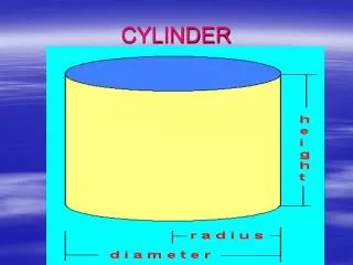
Power Cylinder Metrology Stanley Weng Cylinder Systems Development
Outline • Surface Finish • Measurement Instruments • skidless • skidded • Surface Finish components • Cutoff • Filters • Parameters of Surface Finish • Typical Surface Finish for Cylinder Liner
Outline • Roundness • Measurement Instrument • Harmonic Analysis • Filtering • Roundness Analysis • Reference Circle • Roundness Parameters • Cylindricity • Definition of Cylindricity • Instrument • Cylindricity Analysis
Cylinder Liners / Bores surface finish, bore distortion roundness Piston Rings circumferential waviness, face surface finish, etc. Piston circumferential waviness, groove surface finish, etc. Functional Considerations
Typical Surfaces • Cast • Turned / Bored / Milled • Ground / Honed • Plateau Honed • lapped
Typical Roughness Profiles • Patterned (Turned / Bored / Milled) • Random (Cast, Ground, Honed, EDM) • Stratified (Plateau Honed)
Typical Instrumentation for Surface Finish • Stylus Methods (CTC) • Light Scattering • Optical Focusing (Wyco) • Pneumatic • Area Capacitance • Ultrasonic
Stylus Based Measurement • Skiddless Instruments • Laboratory Applications • Can also evaluate Form & Waviness (Wear Analysis) • Cost : High • Skidded Instruments • “Shop Floor” Applications • Can not evaluate Form & Waviness and Wear • Cost : Low
Skidded Instruments • Advantages • Relatively Inexpensive • Easy setup • Vibration Isolation • Disadvantages • Cannot “see” waviness • Significant errors over peaks.
Aspect Ratio • Vertical and Horizontal Magnifications are typically not the same in plotted profiles. • In other words, the aspect ratio is typically not 1:1.
Components of a Trace • Unfiltered Profile (P) • Form Profile (F) • Waviness Profile (W) • Roughness Profile (R)
Unfiltered and Form Profiles • Piston Ring Groove
Waviness Profile • Form removed from Ring Groove Data
Roughness Profile • Waviness and Form removed
Wavelength Regimes Roughness Waviness Form Process Tool Nose Radius Chatter/Vibration Guideway Straightness Abrasive Size/Density Stiffness Alignment Material Properties Controls Thermal Effects Product Friction Localized Contact Conformability or Fluid Retention Load Carrying Bending (of mating surface) Wavelength (l)
“Cutoff” • The Roughness Cutoff (c) indicates the wavelength which separates roughness from waviness. • The Waviness cutoff (w) separates waviness from form. • Though very functional, this is not often used. • Most instruments do not accommodate w.
Cutoff Selection lc: 8.0 mm Wt = 3.5 µm Ra = 2.16 µm
Cutoff Selection lc: 2.5 mm Wt = 10.4 µm Ra = 0.77 µm
Cutoff Selection lc: 0.8 mm Wt = 14.2 µm Ra = 0.42 µm
Filtering for Roughness • Profile data is filtered to remove waviness and form error prior to roughness assessment. • Two aspects of the filter must be defined : • Filter type • Filter cutoff wavelength
Fourier Analysis • Can be used to determine predominant wavelengths in a data set. • Fast Fourier Transforms (FFT’s) have been historically used in the analysis of roundness data. • The same techniques can be useful in roughness analysis.
Filter Types • 2CR : Electronic Filters • PC - 2CR : Phase Corrected 2CR • Gaussian : Most recent filter. • M1 : Triangular approximation to Gaussian. • Rk (Valley Suppression) : Used for stratified (plateaued) surfaces.
2CR Filters • Resistor-capacitor network used in original instruments. • 75% transmission at cutoff • phase lagging. • Can be implemented in software. • Some instruments refer to as (ISO). • Based on older ISO standards.
2CR - Phase Corrected (PC) • A digital (software) filter which reproduces the transmission of the 2CR filter without phase distortion. • First introduced by Rank Taylor Hobson. Known as the ‘PC’ filter. • 75% transmission at the cutoff.
Gaussian Filters • Named based on Gaussian weighting function used to determine waviness. • Recently introduced in ISO. • ‘Symmetric’ filter in that waviness can be directly subtracted from form to get roughness.
Gaussian Filters • 50% transmission at the cutoff. • ‘Sharper’ in the frequency domain than 2CR. • Can be computationally expensive. • Various ‘fast’ implementations are in use. The most common being the triangle or ‘M1’ filter.
Valley Suppression Filtering (DIN 4776) • Filtering methodology used to remove “valley influences” from waviness profile. • Reduces “push-ups” on sides of valleys.
Valley Suppression Filtering (DIN 4776) • Data is filtered and waviness profile is used to “clip” the valleys.
Valley Suppression Filtering (DIN 4776) • Resulting (clipped) profile is filtered and valleys are re-inserted.
300:1 Bandwidth Implications • 0.8 mm cutoff (c ) • 2.5 µm short wavelength cutoff (s) • 2.0 µm stylus tip radius • 0.5 µm data point spacing
300:1 Bandwidth Implications • 2.5 mm cutoff (c ) • 8.0 µm short wavelength cutoff (s) • 5.0 µm stylus tip radius • 1.5 µm data point spacing
Parameterizing the Profile • Currently there are nearly 300 parameters that have been defined/published for the analysis of surface profiles. • For the most part, these parameters can be grouped into 4 major categories...