Implement Spanning Tree Protocols (STP)
Implement Spanning Tree Protocols (STP). LAN Switching and Wireless – Chapter 5. Objectives. Explain the role of redundancy in a converged network Summarize how STP works to eliminate Layer 2 loops Explain how the STP algorithm uses three steps to converge on a loop-free topology

Implement Spanning Tree Protocols (STP)
E N D
Presentation Transcript
Implement Spanning Tree Protocols (STP) LAN Switching and Wireless– Chapter 5
Objectives • Explain the role of redundancy in a converged network • Summarize how STP works to eliminate Layer 2 loops • Explain how the STP algorithm uses three steps to converge on a loop-free topology • Implement rapid per VLAN spanning tree (rapid PVST+) in a LAN to prevent loops between redundant switches.
Explain the Role of Redundancy in a Converged Switched Network • Describe the role redundancy in a hierarchical network
Explain the Role of Redundancy in a Converged Switched Network • Describe how redundancy can disable a hierarchical network
Explain the Role of Redundancy in a Converged Switched Network • Explain how Layer 2 loops occur in well managed networks
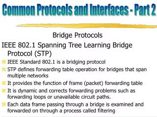
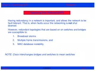
Spanning Tree Protocol (STP) STP runs on bridges and switches that are 802.1D-compliant. There are different flavors of STP, but 802.1D is the most popular and widely implemented. You implement STP on bridges and switches in order to prevent loops in the network. STP is used in situations where you want redundant links, but not loops.
Spanning Tree Protocol (STP) Redundant links are as important as backups in the case of a failover in a network. A failure of your primary activates the backup links so the network continues to function. Without STP on the bridges and switches, such a failure can result in a loop. If two connected switches run different flavors of STP, they require different timings to converge, because it creates timing issues between Blocking and Forwarding states. Therefore, it is recommended to use same flavors of STP.
Summarize How STP works to Eliminate Layer 2 Loops in a Converged Network • Describe the STP algorithm
Bridge • A device that connects two local-area networks (LANs), or two segments of the same LAN that use the same protocol, such as Ethernet.
BPDU • Acronym for bridge protocol data unit. • BPDUs are data messages that are exchanged across the switches within an extended LAN that uses a spanning tree protocol topology. • BPDU packets contain information on ports, addresses, priorities and costs and ensure that the data ends up where it was intended to go. • BPDU messages are exchanged across bridges to detect loops in a network topology. • The loops are then removed by shutting down selected bridge interfaces and placing redundant switch ports in a backup, or blocked, state.
Summarize How STP works to Eliminate Layer 2 Loops in a Converged Network
Port States • STP determines the logical loop-free path throughout the broadcast domain. • The spanning tree is determined through the information learned by the exchange of the BPDU frames between the interconnected switches. • To facilitate the learning of the logical spanning tree, each switch port transitions through five possible port states and three BPDU timers.
Port States • The spanning tree is determined immediately after a switch is finished booting up. • If a switch port were to transition directly from the blocking to the forwarding state, the port could temporarily create a data loop if the switch was not aware of all topology information at the time. • For this reason, STP introduces five port states. • The following provides information on how the port states ensure that no loops are created during the creation of the logical spanning tree.
Port States • Blocking • Listening • Learning • Forwarding • Disabling
Port States - BLOCKING Blocking - The port is a non-designated port and does not participate in frame forwarding. The port receives BPDU frames to determine the location and root ID of the root bridge switch and what port roles each switch port should assume in the final active STP topology. .
Port States - LISTENING Listening - STP has determined that the port can participate in frame forwarding according to the BPDU frames that the switch has received thus far. At this point, the switch port is not only receiving BPDU frames, it is also transmitting its own BPDU frames and informing adjacent switches that the switch port is preparing to participate in the active topology.
Port States - LEARNING Learning - The port prepares to participate in frame forwarding and begins to populate the MAC address table.
Port States - FORWARDING Forwarding - The port is considered part of the active topology and forwards frames and also sends and receives BPDU frames.
Port States - DISABLED Disabled - The Layer 2 port does not participate in spanning tree and does not forward frames. The disabled state is set when the switch port is administratively disabled.
Port States • Blocking • Listening • Learning • Forwarding • Disabling
Summarize How STP works to Eliminate Layer 2 Loops in a Converged Network • The role of the Bridge ID (BID) in STP
Summarize How STP works to Eliminate Layer 2 Loops in a Converged Network How port roles support the operation of STP
Summarize How STP works to Eliminate Layer 2 Loops in a Converged Network • The role of STP port states and BPDU timers in the operation of STP - Bridge Protocol Data Units (BPDUs)
Explain How the STP Algorithm Uses Three Steps to Converge on a Loop-Free Topology • Summarize the 3 step process STP uses to create a loop free topology • STP convergence Steps • Elect a Root Bridge • Elect the Root Port • Elect the Designated and Non-designated ports
Explain How the STP Algorithm Uses Three Steps to Converge on a Loop-Free Topology • The STP decision sequence is used to elect a root bridge for a network
Explain How the STP Algorithm Uses Three Steps to Converge on a Loop-Free Topology • Describe the process of electing a root port on a switch
Explain How the STP Algorithm Uses Three Steps to Converge on a Loop-Free Topology • The process of electing designated ports and non-designated ports on a switch
Implement Rapid per VLAN Spanning Tree (rapid PVST+) in a LAN
Implement Rapid per VLAN Spanning Tree (rapid PVST+) in a LAN • Features of PVST+
Implement Rapid per VLAN Spanning Tree (rapid PVST+) in a LAN
Edge Port Edge ports, the equivalent of PortFast-enabled ports, and point-to-point links are candidates for rapid transition to a forwarding state. However, before the link type parameter is considered, RSTP must determine the port role.
Edge Port Root ports do not use the link type parameter. Root ports are able to make a rapid transition to the forwarding state as soon as the port is in sync. Alternate and backup ports do not use the link type parameter in most cases. Designated ports make the most use of the link type parameter. Rapid transition to the forwarding state for the designated port occurs only if the link type parameter indicates a point-to-point link.
Implement Rapid per VLAN Spanning Tree (rapid PVST+) in a LAN • RSTP edge ports
Implement Rapid per VLAN Spanning Tree (rapid PVST+) in a LAN • RSTP link types
Implement Rapid per VLAN Spanning Tree (rapid PVST+) in a LAN • RSTP port states and port roles
Implement Rapid per VLAN Spanning Tree (rapid PVST+) in a LAN • How to configure rapid PVST+
Implement Rapid per VLAN Spanning Tree (rapid PVST+) in a LAN • How to design STP to avoid problems
Implement Rapid per VLAN Spanning Tree (rapid PVST+) in a LAN • Describe how to identify and solve the key STP configuration issues
Summary • Spanning Tree Protocol (STP) is used to prevent loops from being formed on redundant networks • STP uses different port states & timers to logically prevent loops • There is at least one switch in a network that serves as the root bridge • Root bridge is elected using information found in BPDU frames • Root ports are determined by the spanning tree algorithm and are closest to the root bridge
Summary • STP lengthy convergence time (50 seconds) facilitated the development of: • RSTP • convergence time is slightly over 6 seconds • Rapid PVST+ • adds VLAN support to RSTP • is the preferred spanning-tree protocol on a Cisco switch • network