Download
1 / 20
200 likes | 214 Views
This article discusses the performance of the QMB1 board with a toroidal inductor for distributing light in notched fibre systems. It includes details on the calibration system for SiPM and LED, as well as the results and performance of the QMB1 board.

E N D
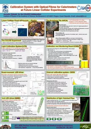
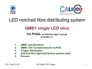
Ivo Polák, on behalf prague’s group polaki@fzu.cz QMB1 performance QMB1 with Toroidal inductor at PCB Trigger distribution Notched fibre light distribution systems 3x24 Resume Calibration system for SiPMandLED notched fibre distributing system Ivo Polák, FZU, Prague
CMB 2003 - 2007 Quasy Resonant systems 2007 - present Members of our group: Physicists: J. Cvach group leader, J. Smolik, J. Zalesak Electoronics: J. Kvasnicka, M. Janata, I. Polak D. Lednicky Two calib. systems since 2003 Ivo Polák, FZU, Prague
Calibration and Monitoring Board (CMB) HCAL 1m2 BT 2006-2009, now WHCAL T=Temp sensor HCAL layer . . . . . . . . . . . . 12 LEDs 12 Photo-diodes • CMB consists of: • 12 UV LEDs, each LED illuminates 18 scintillating tiles • 12 pin-photodiodes preamplifier (LED feedback) • Light flash is steerable in width (2~100ns) and in amplitude • Controlled externally by CANbus, T-calib (LVDS) and V-calib (differential analog signal) • Temperature readout, several sensors are placed on the module Ivo Polák, FZU, Prague June 11, 2011 TIPP 2011, Kvasnicka 3
LED driver on CMB The LED is driven differentially The key component is an IC IXLD02, a LED driver from IXIS company Reverse voltage is applied right after the pulse LED stops to shine immediately Disadvantage: RFI (radio frequency interference) due to the sharp edges Ivo Polák, FZU, Prague June 11, 2011 TIPP 2011, Kvasnicka 4
CMB results • CMD worked well for the 1m3 HCAL phys. Prototype (and still works with WHCAL!) • Used for • Low intensity: the Single Photon Spectrum (gain calibration) • High intensity: SiPM saturation • Temperature measurements (for corrections) Ivo Polák, FZU, Prague June 11, 2011 TIPP 2011, Kvasnicka 5
QMB1 • Quasi resonant Main Board • Modular system, 1 LED per board • DAQ + CANbus control, or stand-alone mode • LVDS Trigger distribution system • Variable amplitude, zero to maximum smooth • Pulse width fixed to abt. 5ns (UV or blue LED) • Voltages and temperature monitor • Width of PCB 30mm, depth 140mm Ivo Polák, FZU, Prague
GET more light! Quasi-Resonant LED driver Longer pulse Larger inductor • Less RFI, not sensitive to magnetic field –tested up to 4T • PCB integrated toroidal inductor (~35nH) • Fixed pulse-width (~4ns) PIN signal 4ns/div To be increased, to get more light. LED current 1V => 1A 1App Ivo Polák, FZU, Prague
6-LED QR driver Main Board = QMB6 Consists: • 6 QR LED drivers • 2 PIN PD preamps • CPU + communication module, CANbus • Voltage regulators • temperature and voltage monitoring Ivo Polák, FZU, Prague 8
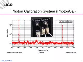
LED, optical power test DC and pulsed Optical Power Meter PM100D with Si sensor S130D by Thorlabs Prague, March 2010 Some LEDs intended to calibration Ivo Polák, FZU, Prague
QMB6 performance 3 mm 5 mm ~200 MIPs Very nice single photon spectrum (due to <3.5 ns pulse) Nice saturation curves (12 LEDs illuminated by 1 LED) We did a test in 4T magnetic field with a minimal effect (<1%) on operation Dynamic range up to 200 MIPs per position LED optical power up to 0.4 nJ per pulse Ivo Polák, FZU, Prague June 11, 2011 TIPP 2011, Kvasnicka 10
Principal schema Larger inductor than the older QMB6 Ivo Polák, FZU, Prague
Signal distribution at 30 x 140 mm^2 Two flat cables, Twisted pair for Trigger Ivo Polák, FZU, Prague
TRIGGER (T-calib) LVDS distribution to QMB1 master slave slave slave slave TX RX Terminated 120ohm Terminated 120ohm LVDS Up to 6 + 6 slaves modules Trigger from DAQ Ivo Polák, FZU, Prague
3D draw of QMB1 T-calib LVDS flat cable LED PWR 15V and CANbus fibre Ivo Polák, FZU, Prague
Mechanical layout of QMB1 LED Outer line: 30 (29) x 140 mm*2 4 mounting holes for M2.5 screw Ivo Polák, FZU, Prague
Notches at one long fibre (24notches total) LED side Notch # 4 Notch # 24 last one, biggest Light coupled from tap Taken on microscope with zoom ~50 Ivo Polák, FZU, Prague
Notched fibre illuminated by green laser pointer Ivo Polák, FZU, Prague
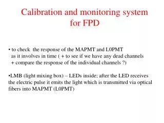
Optical fiber: performance “start” position “middle” position “end” position • We have measured several hand-made notched fiber: • 72 notches: tolerance within 20% • 24 notches: tolerance within 15% • 12 notches: tolerance within 10% • We had a measurement mismatch with a fiber producer We discovered, that the measurement methodology is crucial • Latest measurements of the light yield • Through the 3mm hole on the PCB (FR4 with filled inner layer) • 3 positions of the notch according to the PCB thru-hole Ivo Polák, FZU, Prague June 11, 2011 TIPP 2011, Kvasnicka 18
QMB1 (1-chanel LED driver): Done Topology, PCB design Communicating bus (CAN) CPU (Atmel AVR) Trigger distribution (LVDS) Trigger delay canbe tuned by C trimmer (~10ns) 4 mounting holes for screw M2.5 Fibre(LED) position set to center of PCB PCB in production + assembly To be done Debugging in October/beginning of Nov Set of notched fibers, semiautomat machine under development Set: 3*fibre with 24 notches, creating a line of 72 notches. 3 sets will be delivered in November work at 2011 2010 Idea Ivo Polák, FZU, Prague
Resume • QMB1 is in PCB design stage • Exact position of PCB holes to be defined • Exact UV-LED position, coupling to fibre to be defined • QMB1 in hand with fw - expected in autumn • We are open to collaborate with other group! Ivo Polák, FZU, Prague