Download
1 / 21
210 likes | 235 Views
Discover a cutting-edge diagnostic technique for beam halo imaging using a Digital Micromirror Device (DMD) and adaptive imaging technology. Explore experimental results from University of Maryland Electron Ring and JLAB Free-Electron Laser. Learn about future plans and challenges in high dynamic range imaging systems optimization.

E N D
High Dynamic Range Beam Imaging with a Digital Optical Mask* Presented by Tim Koeth (UMD) on behalf of R.B. Fiorito, H.D. Zhang, A. Shkvarunets UMD, College Park, Maryland S. Zhang, S. V. Benson, D. Douglas, F. G. Wilson JLAB, Newport News, Virginia DITANET Beam Diagnostics Conference November 9-11, 2011, Seville, Spain *Work Funded by US ONR, DOD JTO and DOE Office of HEP
Outline • Introduction • Motivation and Challenges of Halo Measurements • Current diagnostic techniques • New Adaptive Halo Imaging Technique usingDigital Micromirror Device (DMD) • Experimental Results • University of Maryland Electron Ring (UMER) • JLAB FEL • Future Plans
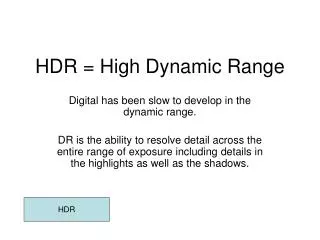
Motivation and Challenges Negative effects of Beam Halo • Beam Loss • Activation of Beam line components • Emittance Growth • Emission of Secondary Electrons • Increased Noise in Detectors • Challenges to diagnostics of halos • Need high dynamic range: >~105 • Adaptive to variable beam core
Previous Experimental Methods Wire Scanner and Scraper Assembly Low-Energy Demonstration Accelerator - LANL DR: 105 Ionization beam profile monitor DR: 103 Passive Spatial Filtering solar coronagraphy applied to beams DR: 106-107 P. Cameron, et al. Proc. of PAC99: 2114-2116, 1999 Imaging Techniques T. Mitsuhashi, EPAC 2004. T.P.Wangler, et. al., Proc. PAC01 High Dynamic Range Camera Spectra-Cam CID $$ DR >105 measured with laser C.P. Welsch, et. , Proc. SPIE 6616,9 (2007).
120 Digital Micro-mirror Device* *DLPTM TexasInstruments Inc. Array dimensions: 14 x 10 mm Pixels: 1024 x 768, Pixel dimension: 14x14 mm Switching rate: 9600 fps Individual pixel addressable Used in HD TV & Projectors Available as development ‘kits’ Optimized to visible, IR, UV
Beam Halo Imaging System using DMD developed at UMD* *R.Fiorito, H.Zhang, A. Shkvarunets, et. al. Proc. BIW2010 Pixels near saturation Beam optical radiation Source Source Mirror Mirror L1 L1 Computer 32 mm Computer L2 L2 L3 32 mm L3 L4 L4 Halo Light Core Light Image 2 900 Frames 180 Frames Camera Sensor Camera Sensor Mask Image 1 DMD DMD Pixels near saturation DR >105 Two compensations are needed, DMD rotated 45o & path length
Scheimpflug compensation Lens Scheimpflug intersection 12 0 24 0 Target reflected light θ φ Micro-mirrors Incident light Image on DMD DMD u v mirror Lens focus length f Image on CCD Image on DMD
DMD Imaging Experiments on University of Maryland Electron Ring (UMER) Screen Screen
Dynamic Range measurement of imaging system Phosphor screen image of 21 mA beam 32mm 20 275 1000 Integration Frames: 290 pixel 2000 3000 5000
0 - 1 Log I/I0 - 2 - 3 - 4 - 5 Dynamic Range Measurement at UMER 32mm 32 mm
Spatial Filtering Ability of DMD Beam on, DMD all on Beam on, DMD all off 32mm 180 180 21 mA beam
Comparison of Images obtained with DMD and Mirror DMD all on (with Scheimplug compensation) Simple Mirror (no compensation) DMD all floating (no compensation)
Quadrupole Screen Quadrupole Induced Halo Experiments on UMER Screen
Demonstration of adaptive threshold masking Quadrupole Current IQ 82.9%IQ 66.3%IQ 49.7%IQ 32mm (a) y x 70 45 45 60 (b) 640 660 250 280
Non Interceptive Beam/Halo Imaging at JLAB using Optical Synchrotron Radiation Bending Magnet Quadrupoles
Quadrupole Scan Using OSR with Tune-up Beam (E=135 MeV, I= 0.32mA: 2Hz rep-rate, 250ms macro, 4.68MHz micro, 135pC/micro ) 4 mm 0 G 500 G -500 G 300 G 0G Quad strength -700 G -1000 G -1700 G -2000 G -2500 G -3000 G
OSR Halo Imaging of JLAB CW beam with DMD threshold mask (I = 0.63 mA, 4.68MHz, 65pc/micropulse, l= 654nm x 90nm , ND=0.4 ) 11.6 mm 0.04 s 0.18 s 11.6 mm 1.6 s 42 s 6.5 s
Reconstructed intensity distribution J(x,y) and calculated total radiant energy ETotal (1- 10-6 ) Jmax (1 -10-2 ) Jmax (10-2 -10-6) Jmax
Summary • Results • Developed and tested high-dynamic range ( DR ~105 ) halo diagnostic imaging system using a phosphor screen + DMD at UMER • Developed a non interceptive OSR DMD imaging system to observe beam halo at JLAB FEL under CW operating conditions; with measured DR > 106 . • Performed quad scan of JLAB tune-up beam using OSR • Future plans • UMER: Do time-resolved halo imaging and multi-turn halo evolution studies at UMER using DMD to study/mitigate factors effecting halo • JLAB: • Short terms: Verify and possibly improve DR >~10(5) of present system • 1a) Improve background measurements and verify halo is not due to stray light from upstream internal sources • 1b) decrease optical magnification onto DMD and /or increase current density via current, focusing/tune; • Long term: Extend DR of halo measurement to limit: • 1) add Lyot and/or apodizing stops to decrease effect of diffraction • 2) improve optical transport with enclosures and antireflection coating on optics port to further reduce any external stray light • Compare emittance measurements using OTR and OSR quad scans • Explore possibility of using DMD to measure halo/core emittances and to do optical phase space mapping (optical analogy of pepper pot technique)