Download
1 / 12
120 likes | 220 Views
Explore Ohm's Law through voltage-current relationships in resistors, series and parallel circuits. Verify theoretical calculations with experimental data to analyze circuit resistance accurately.

E N D
Salahaddin University –ErbilCollege of Education /Physics Department • Lecturer • AssisLec.SanaLatifNahmatullaBarzanje • sana_barzanje@yahoo.com • 2018-2019 Investigation Ohm's Law
Outline • Background • Object • Theory • Combinations of Resistors • Apparatus • Experimental Method • Questions
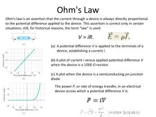
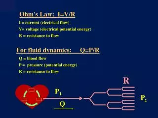
Backgraound A difference of potential is required to produce a current in a circuit. The relationship between potential difference and current, discovered by George Ohm (1787-1854), is perhaps one of the most commonly applied relationships in the analysis of electrical circuits. Ohm’s law is not a fundamental law, but it is applicable to a certain class of materials called “ohmic” conductors. Materials which do not follow Ohm’s law are said to be “nonohmic”. Semiconductors exhibit nonohmic behavior.
Object To verify Ohm's law by plotting voltage versus current for several know resistances.
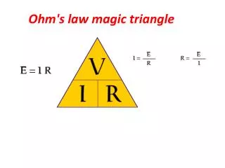
Theory Ohms low is one of the most important laws in electricity. It states that the potential difference across the ends of a conductor is directly proportional to the current passing through it, with the temperature kept constant. So: V = RI where R is the resistance.
Combinations of Resistors Resistors can be combined in simple circuit arrangements that increase or decrease the overall resistance in the circuit. These arrangements are called series and parallel circuits. Figure (2a) illustrates two resistors connected in series and Figure (2b) shows the resistors in a parallel arrangement. In order for charges to move in a conductor, there must be a potential difference across the conductor. In order for charges to move through a circuit, there must be a complete path leading away from and back to the source of emf (VAB in Figure 1). As you can see, in the series arrangement shown in Figure (2a) the current I in the circuit goes through each resistor. If we compute the potential drop V1 across R1 using Ohm’s Law, it is merely V 1 = IR 1. Likewise, the drop across R2 is V2 = IR2. The potential drop across both resistors is VAB = V1 + V2. One can think of the applied voltage VAB being divided between the two series resistors R1 and R2.
In the parallel arrangement shown in Figure 1(b), however, the current divides at the junction A and recombines at junction B. Therefore, the current through R1 and R2 may be different. Notice that in this case VAB = V1 = V2. That is, the potential drop across each resistor is the same. Using some simple algebra and your understanding of the potential drops in a simple series or parallel circuit, the relationships for determining equivalent resistance for resistors in series and/or parallel can be derived. These relationships are: a) Series: the equivalent resistance is: Req=R1+R2 … (1) b) Parallel: the equivalent resistance is: (The reciprocal of the equivalent resistance is the sum of the reciprocals of the individual resistances.) As suggested in Eqs. (1) and (2), the sums include a term for each resistor in the circuit.
Apparatus • Variable DC voltage supply, resistor, connecting wires, analog ampermeter, digital multimeter.
Experimental Method • Connect the circuit shown in Figure (1), using the resistor labeled as “50 Ω” or “100 Ω” or “200 Ω” or “as you like” on the circuit board. • Using a resistance change the current used and observe the change in the potential difference. • Repeat step (2) for different value of (I) and (V) and tabulate them. • R= …… Ω • V (Volt) I (Amper) • Plot a graph between the value of (V) at Y-axis and corresponding values of (I) on X-axis where the slope [ Slope= ΔV/ΔI] of the straight line represents the value of the used resistance [R=Slope]. • Compute the percent error between the measured and calculated value. Record this on the worksheet. • The percentage change in resistance as: • Repeat step (1, 2, 3, 4, and 5) for two different resistances connected in series and parallel as shown in Figures (2a) and (2b) respectively. • Plot the results obtained in step (6) in two different graphs, take their slope where could be compared with their theoretical value.
Questions 1- What conclusion can you draw from the plot of your data? 2- Does your measured resistance value agree with the accepted value within the calculated range? 3- Find the Percent error of each circuit? 4- A walkman uses a standard 1.5 V battery. How much resistance is in the circuit if it uses a current of 0.01 A? 5- The 100 Ω resistance value given for the resistor used in the experiment is only 6- Approximate. What is the resistance value determined from your data?