Download
1 / 41
420 likes | 773 Views
Rotorcraft Design II: Preliminary Design. Dr. Daniel P. Schrage Professor and Director, CERT & CASA School of Aerospace Engineering Georgia Tech, Atlanta, GA. Course Outline. Review of Conceptual Design Solutions Conceptual Design Issues for Resolution Structural Design Dynamics

E N D
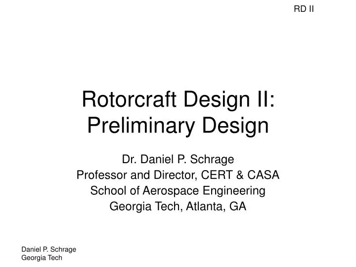
Rotorcraft Design II:Preliminary Design Dr. Daniel P. Schrage Professor and Director, CERT & CASA School of Aerospace Engineering Georgia Tech, Atlanta, GA
Course Outline • Review of Conceptual Design Solutions • Conceptual Design Issues for Resolution • Structural Design • Dynamics • Stability and Control • Drive System Design • Life Cycle Cost • Power Plant Selection and Installation • Secondary Power Systems • Weight and Balance • Maintainability • Reliability and Availability • Configuration and Arrangement
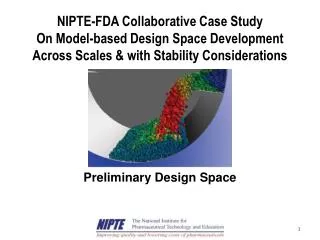
Georgia Tech Evolving Rotorcraft Preliminary Design Methodology PRODUCT DEVELOPMENT PRODUCT DEVELOPMENT PROCESS DEVELOPMENT PROCESS DEVELOPMENT Baseline Vehicle Manufacturing Requirements Baseline Upgrade Virtual Product Data Model Selection Processes Analysis Targets Management (GT-IPPD) (DELMIA) (RFP) (ENOVIA) Vehicle Assembly New Design Upgraded/Derivative. Design Preliminary Vehicle Processes Configuration Geometry (DELMIA) (CATIA) Aerodynamic Support Processes Vehicle Sizing & Performance Vehicle Engineering (DELMIA) Performance Analysis (BEMT) Analysis (RF Method) (CATIA) Propulsion (GTPDP) Performance Vehicle Operation Analysis Safety Processes Linear Static (DELMIA) Noise/Vibration Structural Analysis Characteristics (CATIA-ELFINI) Analysis (LMS) FAA Certification Multi-Body, Non-Linear Dynamic Analysis (DYMORE) Reliability Modeling Linear & Non-Linear (PRISM) Structural Analysis (NASTRAN/ABAQUS) Revised Preliminary Conceptual Design Cost Analysis Stability and Control (CATIA) (PC Based Cost Analysis Model) (MATLAB/LMS/CATIA) Light Helicopter- Overall Evaluation GTX Criterion Function Final Proposal
Present Conceptual and Preliminary Design Approach Product Development Process Development Requirements Analysis (RFP) FAA Certification/ Mil Qualification Baseline Model Selection (IPPD) Baseline PDS Targets Manufacturing Processes CBEM Engine Model Geometry/Static Analysis (CATIA) Operations & Support Processes Vehicle Sizing & Performance (RF Method) (GTPDP) Safety Processes Dynamic Analysis (DYMORE) Structural Analysis (NASTRAN) Reliability Modeling (PRISM, etc.) Stability and Control Analysis (MATLAB) Preliminary Design Cost Analysis (PC Based Cost Model) ITU LCH Final Design Overall Evaluation Criterion Function
2003 AHS Student Design Competition: VTOL Urban Disaster Response Vehicle (VUDRV)(Sponsored by Sikorsky Aircraft and NASA) • Critical Milestones • Response Requirements • Competition Judging Criteria • Conceptual Exploration Status • Conceptual Design Issues for Resolutions • Recommended Conceptual and Preliminary Design Approach
VUDRV Critical Milestones • Release of RFP: October 21, 2002 • Notice of intent to Compete: October 28, 2002 • Teleconference w/Sikorsky: Oct 30,2002 on Problem Statement • Additional teleconferences: As Required • 2 page emerg results sumry: Feb. 15, 2003 • Final report due: June 15, 2003 • Winners announced: August 1, 2003
VUDRV Response Requirements • A written report limited to100 pages shall provide the following: • Executive Summary (5 page summary of entire report & key findings) • Description of operational environment and mission requirements (add critical requirements identified during concept exploration) • Detailed mission profiles shall be recommended for the following missions: • High rise Firefighter deployment • Roof Occupant extraction • Building face penetration and occupant recovery • Ground pump water cannon fire fighting • Self contained tank water cannon fire fighting • Disaster command and control
VUDRV Response Requirements • A written report limited to100 pages shall provide the following (continued): • Concept evaluation and down-selection process and rationale • Selected Concept Preliminary Design • Overview including concepts sketches in each mission role • Day in the life of the system description • Timeline from 911 call to end of day • Vehicle Subsystem descriptions • (airframe, rotors, drive, controls, avionics, landing gear…) • Include rationale for recommended subsystem technical approach • Avionics system description including proposed operator interface • Mission kit descriptions as required for each mission • Weight empty derivations for primary vehicles • Mission gross weight derivations for each mission • Performance estimates and plots for each mission • Such as time on station vs number of occupants recovered for building face extraction
VUDRV Response Requirements • A written report limited to100 pages shall provide the following (continued): • Compliance matrix showing compliance with all technical/mission requirements • Non-recurring and recurring unit cost estimates • Development schedule • Risk identification and Risk Reduction plan • Recommendation of how many systems would be required per 100,000 person city population • Concept sketch of future urban fire station with mix of ground vehicles and proposed system(s)
VUDRV Competition Judging Criteria • Innovation: 40% • Study shows ability to depart from conventional thinking and paradigms to explore potentially high value solutions • Understanding of the Problem: 10% • Study clearly demonstrates understanding of the real world mission problem and the associated technical challenges • Technical Content: 30% • Analysis and data is accurate and all methods used are well understood. Underlying principles are well understood. • Clarity: 20% • Report is clear, concise, and develops compelling case for proposed solution. Emphasis is on clear graphics and diagrams to illustrate points and concepts
Review of VUDRV Conceptual Exploration Status • Conceptual Design Selection still incomplete; however, not a problem based on RFP Requirements which places more emphasis on requirements, mission and operational analysis • Initial Requirements Analysis well done and resulted in initial functional and resulting performance requirements • More detailed mission and operational analysis required to further verify the performance requirements for concept selection
High-rise Firefighter Deployment 15 Fire Fighters to Rooftop 2 minute Cycle Rooftop Occupant Extraction 1200 People/Hour Building Face Penetration / Occupant Recovery 800 People/Hour Ground Pump Water Cannon Fire Fighting Lift 5” Diameter Hose 1000 feet Onboard Tank Water Cannon Fire Fighting 500 Gallon Tank; Refill in 60 seconds Disaster Command and Control Occupant Locator Information Gathering / Transmitting Define the Problem Requirements Analysis VUDRV Modes of Operation
Define the Problem Requirements Analysis VUDRV Operational Scenarios
Define the Problem Requirements Analysis Operational Scenarios VUDRV High-rise Firefighter Deployment
Define the Problem Requirements Analysis Operational Scenarios VUDRV Rooftop Occupant Extraction
Define the Problem Requirements Analysis Operational Scenarios VUDRV Building Face PenetrationOccupant Extraction
Define the Problem Requirements Analysis Operational Scenarios VUDRV Water Cannon Fire FightingGround Pump
Define the Problem Requirements Analysis Operational Scenarios VUDRV Water Cannon Fire FightingOnboard Tank
Define the Problem Requirements Analysis Operational Scenarios VUDRV Disaster Command & Control
Define the Problem Requirements Analysis VUDRV Utilization Environments • Urban Canyon • Low to Zero Visibility • Turbulent Air • High Temperature Exposure • Extreme Weather Conditions • Road Transport
Define the Problem Requirements Analysis Mission 300 lb Person 200 lb Person Internal (assumed) Module (assumed) Persons Water External Total FFD 15 0 612 1,000 4,500 0 5,500 6,112 RTOE 0 70 612 1,000 14,000 0 15,000 15,612 BFPOE 2 70 612 1,250 14,600 0 15,850 16,462 DWCFFgp 0 0 612 750 0 8,500 9,250 9,862 DWCFFip 0 0 612 750 0 4,164 4,914 5,526 CAC 0 4 612 2,000 800 0 2,800 3,412 VUDRV Functional Requirements Payload Capacity
Define the Problem Requirements Analysis VUDRV Performance Requirements Useful Load: 16,500 lbs. Forward Speed: 60+ knots VROC5500 lbs.: 2500 ft/min Hover Ceiling: 7,000+ ft ASL OEIHOVER: 6000 ft ASL / 16,500 lb. Endurance: 1 hr. hover / 1 hr. cruise
VUDRV Conceptual Design Issues for Resolution • Is a new or derivative aircraft the preferred solution? (depends on the time frame when the system must be operational) • The system is more than the vehicle; emphasis is on addressing the ‘system of systems’ • Strong emphasis must be placed on reconfigurability of the system for the different missions • Strong emphasis must be placed on automatic flight control and sensor sub-systems
Recommended Conceptual and Preliminary Design Approach • Should spend substantial more effort on completing the Conceptual Exploration and Design Effort • Need to reach a decision on new or derivative system for the air vehicle (suggest telecon with Andy Keith, Sikorsky) • Explore the use of the ASDL Mission and Unified Tradeoff Environment (UTE) for evaluating combinations of requirements, concepts and technologies (See Dr. Dan DeLaurentis, ASDL, A. Baker Ph.D Thesis)
Requirements (Mission) Space • Concept Space - vehicles attributes used as factors in DoE, built around baseline vehicle • Technology Space - technology metric dials used as factors in DoE, built around baseline vehicle • Mission Space • Compatibility with Concept Space and Technology Space • Mission requirements used as factors in DoE, built around baseline vehicle • Based on a Master Mission Structure which captures primary missions and provides reference point for understanding mission parameter effects on system sizing. • Allows capture of multiple missions and provides continuous mission space • Secondary missions flown after sizing to determine performance
Cruise 3 Combat Radius Cruise 1 Combat Radius Cruise 3 Temperature Cruise 1 Flat Plate Drag Area Cruise 3 Altitude Cruise 3 Cruise 1 Cruise 2 Taxi / Warm-up Mid Hover (OGE) Hover 2 (OGE) Hover 1 (OGE) Drop Payload Hover 1 Time Hover 2 Time Payload Dropped Vertical ROC Payload Common Requirements Fuel Reserve Altitude Best Endurance Velocity Temperature Time 30 min Master Mission Structure
Functionally Relating Responses and Inputs Top-Level requirements related to the mission Objective (O) or System Level Attribute (SLA) Vehicle Attribute Variables Response = fcn (Requirements, Concepts, Technologies) • Potentially large number of inputs; • To cope, evaluate response in “snapshots”, where most inputs are held constant while a subset of the inputs varies • Each “snapshot” computes “deltas” in responses with respect to a baseline • This approach allows the additive combination of the effects of concepts, technologies, and requirements on the decision-making space Technology Dials (related to product and/or process)
Unified Tradeoff Environment • What is needed is a design environment that allows the designer to assess the simultaneous impact of changes in mission requirements, vehicle attributes and technologies while being amenable to probabilistic techniques. • Whether constructed as an integrated environment or built from individual spaces this design environment is called the Unified Tradeoff Environment (UTE). • Integrated UTE • Multi-Space UTE • Most logical breakdown considers design spaces already created. • Concerns with multiple spaces.
Technology Space Mission Space Concept Space ? ? Mission Requirements Vehicle Attributes Technology Dials Responses Responses Responses D D D Concerns with Multi-Space UTE Rbaseline + Engineering Knowledge/Analysis Codes Modified Screening Test Sizing Variables • Independence - Correlation • Across-Design-Space Interactions • Sizing Effects
ITU LCH Conceptual and Preliminary Design Effort • Baseline Istanbul Technical University (ITU) Light Commercial Helicopter (LCH) Prototype Requirements • Status of ITU LCH Conceptual Design effort • Proposed approach for conducting the ITU LCH Preliminary Design effort
Baseline ITU Light LCH Prototype Requirements • A Challenging set of requirements were provided to GIT and ITU Student Design Teams • Results from GIT and ITU individual and team design efforts appear to substantiate the feasibility of meeting the requirements • A baseline ITU LCH Conceptual Design has been established • Some refinements to the ITU LCH Conceptual Design will be made and an ITU LCH Product Design Specification (PDS) established
GTX-Pegasus Three View Depiction (MD-500E Derivative – Not ITU LCH Baseline)
ITU LCH Conceptual Design Status • The ITU LCH Conceptual Design is nearly complete and will be by the end of January 2003 • A Product Design Specification (PDS) will be prepared to document the ITU LCH Conceptual Design • The ITU LCH Preliminary Design Effort will be initiated based on the PDS
Proposed approach for conducting the ITU LCH Preliminary Design effort • The PD Approach is illustrated in the following figure and will emphasize the Product Development (Left Side) process • Will be conducted jointly by ITU and GIT Faculty, Research Engineers, Post Docs, and Students over the next four months • Will include Monthly In Process Reviews (IPRs) to review and approve the status and configuration for the ITU LCH
ITU LCH Preliminary Design Approach Product Development Process Development Requirements Analysis (RFP) FAA Certification/ Mil Qualification Baseline Model Selection (IPPD) Baseline PDS Targets Manufacturing Processes CBEM Engine Model Geometry/Static Analysis (CATIA) Operations & Support Processes Vehicle Sizing & Performance (RF Method) (GTPDP) Safety Processes Dynamic Analysis (DYMORE) Structural Analysis (NASTRAN) Reliability Modeling (PRISM, etc.) Stability and Control Analysis (MATLAB) Preliminary Design Cost Analysis (PC Based Cost Model) ITU LCH Final Design Overall Evaluation Criterion Function
Planned ASD ITU LCH PD Support • The following design support activities are planned in conjunction with the ITU LCH Design Team: • Development of the Initial Product Design Specification (PDS) – completed by end of January 2003 • Conceptual Designs for the ITU LCH – Baseline Conceptual Design completed in GTPDP by end of January 2003, to include airfoil, blade planform, and baseline engines (turboshaft and piston/rotary) • Rotor Airfoil & Blade Planform Trade Study – Complete by 15 February 2003 • Develop DYMORE Dynamic Model of ITU LCH Rotor by 15 February 2003 • Develop a CATIA Model of the ITU LCH by 15 February 2003 • Conduct Stability & Control Analysis for the ITU LCH by 15 March 2003 • Conduct Structures & Dynamics Analysis for the ITU LCH by 15 April 2003 • Finalize the Preliminary Design and Complete & Deliver the ITU LCH Final Report by 15 May 2003