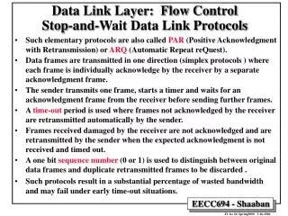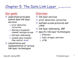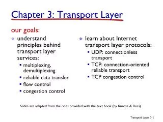
data link Control layer (DLC) – error detection codes
data link Control layer (DLC) – error detection codes. Data link layer (DLC) and lower. Error detection. Network Layer. Network Layer. Error correction. Deliver packets in order and error free. Data Link Layer. Data Link Layer. header. Packet. Trailer. Virtual unreliable bit pipe.

data link Control layer (DLC) – error detection codes
E N D
Presentation Transcript
Data link layer (DLC) and lower Error detection Network Layer Network Layer Error correction Deliver packets in order and error free Data Link Layer Data Link Layer header Packet Trailer Virtual unreliable bit pipe Physical Interface Physical Interface Synchronous bit pipe Intermittent synchronous bit pipe Physical communication link Asynchronous character pipe Subject to transmission errors
Error detection in DLC • Packet transmission errors can not be detected by analysis of the packet itself (why?) • Extra bits must be appended to a packet to detect errors • Error detection techniques • Parity check • Cyclic redundancy check (CRC) • Once errors are detected, receiver can request a re-transmission
Single parity checks • Append a single bit to the packet • Has the value ‘1’, if the number of ‘1’ in the packet is odd • Has the value ‘0’, otherwise • Results in a bit stream that contains even number of ‘1’s • Can detect any single error in the bit string • Can also detect add odd number of errors, but not even number of errors • Noises are sometimes bursty - a number of consecutive errors may occur due to some noise • Single parity check is not effective in detecting multiple errors
Single parity check • 1101000 1101000 1 • 1110010 1110010 • Probability of undetected error (assume errors are independent) Parity check bit 0 p: error probability N: packet length (bit string length)
Horizontal and vertical parity checks • 2-D version of single parity check Horizontal check Vertical check • Not able to detect four bit errors in a rectangular configuration • The overhead: (N+1)*(M+1) - NM
Error check codes • Effectiveness of a code is usually measured by: • Minimum distances of the code • Burst detecting capability • The probability that a random string will be accepted as error free • Error check codes can be used to correct certain errors header anddata Parity checks Code word
Cyclic Redundancy Checks (CRC) • CRC is the most commonly used parity check codes in DLCs • Information bit string M (K bits) • Generator string is G (L bits) • Find the remainder of R = M×2L-1/G, code word is then M×2L-1+R header anddata - M Check bits - G K bits L bits Codeword(K+L bits)
Typical generator string/polynomials • CRC-16 • x16 + x15 + x2+ 1 • used in HDLC • CRC-CCITT • x16 + x12 + x5 + 1 • CRC-32 • x32 + x26 + x23 + x22 + x16 + x12 + x11 + x10 + x8 + x7 + x5 + x4 + x2 + x + 1 • used in Ethernet
Cyclic Redundancy Checks (CRC)Long division & shift register • CRC Can be generated with a shift register with feedback • The feedback itself is controlled by the generator string G header anddata Check bits K bits L bits • gL-3 • gL-2 • g0 • g1 • g2 Bits in Bits out L SRs and feedbacks
Cyclic Redundancy Checks (CRC)Long division & shift register • Information bit string M: 110101 • Generator string is G: 1001 (4 bits) • Find the remainder of R = 011, code word is then 110101011 1 1 0 0 1 1 1 0 1 1 1 0 0 1 1 0 1 0 1 0 0 0 1 1 1 0 1 0 1 1 1001 110101000 01000 s0 s1 s2 s3 1001 01000 1001 1100 1001 01010 1001 0011
Cyclic Redundancy Checks (CRC) • Let • T be the code word • M be the information string, and has K bits • R be the check bits, and has Lbits • T = M*2L + R, can be divided by generator string G • T is transmitted, and if at the receiver side, the received string T’ can still be divided by G, then there is no error, otherwise there must be errors • The selection of G is critical in the effectiveness of CRC
Physical layer error characteristics • Most Physical Layers ( communications channels) are not well described by a simple BER parameter • Most physical error processes tend to create a mix of random & bursts of errors • A channel with a BER of 10-7 and a average burst size of 1000 bits is very different from one with independent random errors • Example: For an average frame length of 104 bits • random channel: E[Frame error rate] ~ 10-3 • burst channel: E[Frame error rate] ~ 10-6 • Best to characterize a channel by its Frame Error Rate, but it is difficult