Download
1 / 1
10 likes | 88 Views
Investigating 3-D structures of cosmic spherules vs. chondrules from meteorites for insights into their formation process through high-speed rotation and shape instability. The study compares external shapes, internal structures, compound formations, and rotation rates, providing valuable data on the cosmic objects' origins.

E N D
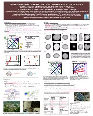
a c THREE-DIMENSIONAL SHAPES OF COSMIC SPHERULES AND CHONDRULES:COMPARISON FOR CHONDRULE FORMATION PROCESS.A. Tsuchiyama1, T. Yada2, and T. Noguchi3, T. Nakano4 and K. Uesugi51Department of Earth and Space Science, Osaka University, 1-1 Machikaneyama-cho, Toyonaka, 560-0043 JAPAN, akira@ess.sci.osaka-u.ac.jp2 Laboratory for Space Sciences Physics Department, Washington University, St. Louis, MO 63130-4899, USA3Department of Material Sciences and Biological Sciences, Ibaraki University, 2-1-1 Bunkyo, Mito, 310-8512 JAPAN4Institute of Geoscience, National Institute of Advanced Industrial Science and Technology, Tsukuba, 305-8567 JAPAN5SPring-8, Synchrotron Radiation Research Institute, Mikazuki, 679-5198 JAPAN. INTRODUCTION ・3-D structures of chondrules of the Allende meteorites (Tsuchiyama et al., 2003) External shapes: bimodal distribution (oblate and prolate chondrules) (Fig.1) Internal structures: distribution of metal/sulfides and voids in oblate chondrules (Fig.2) metal/sulfide grains: apart from the minor axis voids: near the minor axis The above features can be explained by rotation of molten chondrules (Fig.3). The rotation rates are estimated to be 100-500 rps (Fig.7). This high-speed rotation is consistent with a shock wave model (Susa and Nakamoto, 2002). ・This study Cosmic spherule as another type of spherulitic objects formed by shock wave melting 3-D structures of cosmic spherules? → comparative study for chondrule formation process RESULTS ・3-D shapes of the cosmic spherules Prolate spherules are abundant (prolate barred olivine (Fig.5ab) and oblate porphyritic spherules (Fig.5cd)) (Fig.6). Various shapes are present: dumbbell-shape (Fig.5ef), object with projections (Fig.5gh), distorted shape, etc. Compound spherules are not rare (Fig.5ij). Large voids are sometimes present on the surfaces (Fig.5kl). In some prolate spherules, four ridges are running from one of the poles (ridge structure: Fig.5mno). Abrasion? ・Three-axial ellipsoid approximation for rounded spherules Bimodal distribution similar to chondrules (Fig.6) Estimted rotation rates for oblate spherules: >500 rps (Fig.7) (e) (f) (a) (b) (c) (d) fission ・Three-axial ellipsoid approximation a-, b-, and c-axis axial length: A≥B ≥C Degree of oblate/prolate, n (C/B)=(B/A)n oblate: A=B>C log n → ∞ prolate: A>B=C log n → -∞ Aspect ratio, p p = C/A sphere prolate (g) (h) (i) (j) (k) (l) flattening by rotation shape instability by rotation oblate Figure 1. 3-D shapes of chondrules determined by X-ray microtomography (Tsuchiyama et al., 2003). Condrules are taken from the Allende meteorite (CV). The chondrule shapes are approximated as three-axial ellipsoids. This C/B vs. B/A plot shows a bimodal distribution: slightly elongated oblate/prolate chondrules (p=0.85-0.98) and largely elongated prolate chondrules (p=0.74-0.78). This feature can be explained by shape instability due to high-speed rotation (Chandrasekhar, 1964). (m) (n) (o) Figure 5. Bird’s-eye view pictures and CT slice images of spherules. (a) (b) Prolate, barred olivine (504041: 79.8x87.6x123.6 mm, 113.1 mm CT image width). (c) (d) Oblate, porphyritic (NQ6: 132.4x161.6x164.2mm, 167.5 mm CT image width). (e) (f) Dumbbell-shaped, dendritic (To5073: 88.2x113.6x314.4 mm, 116.5 mm CT image width). (g) (h) Spherule with projections, cryptocrystalline (To310042: 193.2x220.0x228.4 mm, 214.5 mm CT image width). (i) (j) Compound, barred olivine (large) and cryptocrystalline (small): 169.0x193.2x228.6 mm, 184.0 mm CT image wieth). (k) (l) Spherule with voids, cryptocrystalline (NC5: 119.6x124.6x149.2 mm, 130.0 mm CT image width). (m) (n) (o) Prolate spherule with ridge structure (NI6: 148.4x166.8x208.2 mm, 169.0 mm CT image width). Figure 2. Distribution of metal/sulfide grains and voids in oblate chondrules. The moment of inertia for the grains (or voids) around the minor axis of the oblate chondrule, M, normalized by that of randam distribution, Mr, is plotted against the degree of oblate, log n. M/Mr>1 and M/Mr<1 for large log n shows concentrations of the metal/sulfide grains apart from and voids near the minor axis, respectively. voids metal/sulfide grains Figure 6. 3-D shapes of spherules (solid symbols) in comparison with chondrules (open symbols). The distribution for the spherules can be also explained by high-speed rotation of molten spherules and the shape instability. Dumbbell-shaped spherules (Fig.5ef) are also consistent with high-speed rotation. The similarity among the cosmic spherules and chondrules may suggest the common formation processes, shock wave melting. However, details are different. For example, prolate objects are more abundant than oblate ones for cosmic spherules while oblate objects are more abundant than prolate one for chondrules. Figure 7. The equatorial radius of the oblate spherules and chondrules, A, are plotted against the aspect ratio, p. The ranges of rotation rates estimated from the equilibrium between the surface tension and centrifugal forth (Chandrasekhar, 1964) are shown in the diagram. The estimated rotation rates of cosmic spherules are larger than those of chondrules due to the smaller sizes of the cosmic spherules than the chondrites. Figure 3. The shapes and the distribution of metal/sulfide grains and voids in oblate chondrules (Fig.2) can be explained by rotation during melting. EXPERIMENTS ・Samples Thirty one cosmic spherules collected from Antarctica by JARE ・X-ray microtomography (Fig.4) Projection CT system (SP-mCT) at SPring-8 BL47XU and BL20XU (Uesugi et al., 1999, 2001) Photon energy: 10-13 keV 3-D image: 300-600 slices Spatial resolution: <1.0-1.5 mm (voxel size: 0.5x0.5x0.5 and 0.23x0.23x0.23 mm) DISCUSSION ・Bimodal distribution of the external shapes similar to chondrules This may suggest the common origin for the both spherulitic objects in the space. ・Cosmic spherule formation as natural experiments for chondrule formation? Possible Chondrules: shock wave melting in the primordial solar nebula (shock wave source?) Cosmic spherules: shock wave melting during entry to the Earth’s atmosphere However, details are different (Table 1). Both chondrules and cosmic spherules were formed by shock wave melting with different shock conditions. or Chondrule formation process is different from shock wave melting. ・Detailed investigation based on the shock wave model required ! BL47XU Table 1. Comparison between chondrules and cosmic spherules. BL20B2 BL47XU Figure 8. A barred olivine chondrule with dumbbell- or torus-like shape (Fig.6-16 in Norton (2002) ). CONCLUSION ・3-D structures of cosmic spherules were examined by microtomography. ・The general shapes are similar to chondrules. This may suggest the common formation origin (shock wave melting) for these two spherulitic objects in the space. ・However, the details are different. ・This may be due to the same process with different shock conditions or non shock wave origin for chondrules. Figure 4. SPring-8, third generation synchrotron facility in Japan, (right) and a projection CT system, SP-mCT, at BL47XU (right). In this CT system (Uesugi et al., 1999, 2001), transmitted X-rays are converted by a fluorescent screen into visible light beams, enlarged by optical lenses, and detected by a CCD camera.