Download
1 / 105
1.16k likes | 1.7k Views
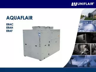
AQUAFLAIR ERAC ERAH ERAF. Aquaflair ERA series. The new ERAC chillers, ERAH heat pumps and ERAF units with free-cooling system, feature state-of-the-art technology ensuring maximum reliability, safety, quiet operation and respect for the environment. Refrigerant: R410A

E N D
AQUAFLAIR ERAC ERAH ERAF
Aquaflair ERA series The new ERAC chillers, ERAH heat pumps and ERAF units with free-cooling system, feature state-of-the-art technology ensuring maximum reliability, safety, quiet operation and respect for the environment. Refrigerant: R410A Cooling Capacity: 50 – 110 kW ERAC Air-Cooled Water Chiller with Axial Fans ERAH Air / Water Heat Pump with Axial Fans ERAF Air-Cooled Water Chillers with Axial Fans and Free-Cooling System
1600 1400 1200 1000 800 kW 600 400 200 0 Aquaflair ERA series 50 – 110 kW
Aquaflair ERA series 120 110 100 90 kW 80 70 60 50 40 0521A 0621A 0721A 0821A 0921A 1021A 1221A 0922A 1022A 1222A
Fans Non ducted Ducted Aquaflair ERA series
Aquaflair ERA series Axial fans Cooling only ERAC Heat pump ERAH Free-cooling ERAF
Aquaflair ERA series Ducted fans Cooling only ERCC Heat pump ERCH Free-cooling ERCF
Overview The AQUAFLAIRERAC/H/F series is composed of ten chillers with nominal cooling capacities ranging from 50 to 110 kW. The various versions can be managed by a UECH 400 control (microprocessor and local user terminal in a single element) or by a UpCO1m system composed of a basic interface board and a local user terminal. The UECH control allows remote control but doesn’t permit connection to the Uniflair supervision system; the UpCO1m is suitable for configuration with a LAN card, I/O contact, clock card, RS485 serial adapter for connection to the Uniflair supervision system or a BMS (Building Management System). Hermetic scroll compressors, environmentally friendly R410A refrigerant and an electronic thermostatic valve (in versions with UpCO1m control) allow increased energy efficiency in all operating conditions.
R410A Refrigerant R410A gas, whose behaviour is almost azeotropic (vapour and solution have the same concentration), is characterized by the absence of glide during state changing phases, which thus occur at a constant pressure without energy loss. The greater thermal exchange capacity and a considerable reduction in the load loss, mean it is possible to install compact components with the same power output, thus benefiting from significant reductions in volume and a considerable increase in efficiency.
R410A Refrigerant • Less pressure drops: • – 20%* in the condenser • – 40%* in the evaporator • Better exchange capacity (internal) • +35%* • +50%** • Hardly any glide • * Compared to R22 / ** compared to R407C
R32 R125 R410A Refrigerant Easier to service R410A • Simplicity and speed of maintenance • R410A • No need to remove all of the gas in the event of a leak • E.E.V. • Monitoring refrigerant leaks Same vapour pressure In the event of a leak the blend composition remains unchanged
Accessibilityto the maincomponents Simplicity and speed of maintenance Electrical sect. • Panels equipped with quarter-turn fasteners and handles • Upper panel is not riveted • Dedicated access for: • Compressors and refigerant circuits • Water tank • Pump group • Pumps Hydraulic sect. Refrigerant sect.
Maincomponents • ELECTRICAL PANEL • The panel conforms to EC directives and features: • IP54 protection grade; • 12 / 24 V and 230 V auxiliary transformer; • General door interlock switch; • Thermo-magnetic protection for the compressors, fans and auxiliaries; • Remote control switches for the compressors; • Anti condensation heaters; • Motor protection for the pump/s and the free cooling pump (ERAF).
Maincomponents • MICROPROCESSOR CONTROL • For the ERAC/H/F chillers and heat pumps the following types of control are available: • UECH • UpCO1m • UECH CONTROL • The UECH microprocessor control is integrated with the local user terminal where the regulation software is housed. This control includes the following components: • User terminal with LCD display and signal lights; • Outlet chilled water temperature regulation; • Anti-freeze protection; • Free-cooling management (ERAF); • Protection and timing of compressors and pumps; • Modulating condensing pressure control; • Total / partial heat recovery management; • High pressure transducers; • Alarm code signalling and centralisation for general alarm reports as a clean contact; • Remote cycle inversion control (ERAH) • ON-OFF remote control.
Maincomponents • UpCO1m CONTROL • The UpCO1m control system consists of two sections: • a control board which consists of one I/O board containing the regulation software and which is fitted on the electrical panel of the unit; • a User Terminal which consists of a user interface and which can be installed locally or remotely. • Features: • 16 bit microprocessor, 14 MHz, internal registers and operations at 16 bit, 512 byte of internal RAM; • Flash Memory up to 2 Mb per programme; • 128 kb static RAM; • RS485 serial output for LAN; • 24 Vac/Vdc power supply; • Telephonic connection for the user terminal; • LED indication of power supply.
Maincomponents COMPRESSORS All the units are equipped with two highly efficient hermetic Scroll compressors with a low sound power level and integrated thermal protection. ERAC/F units with the suffix **21 are provided with two compressors connected in parallel on the same refrigerant circuit: the unit therefore features two partialisation steps, ensuring modulation of the cooling capacity. WATER SIDE EXCHANGER The direct expansion brazed plate evaporator / condenser is entirely made of stainless steel and features counter flow. The exchange surface is configured in such a way as to maximize the exchange coefficient with reduced pressure drops. The inlet and outlet connections are equipped with air bleeding and draining. The closed-cell expanded neoprene insulation prevents the formation of condensation and reduces heat dispersion.
Maincomponents AIR SIDE EXCHANGER The condenser (evaporator) is sized in order to operate at high ambient temperatures, it is composed of a finned pack exchange coil with aluminium fins and mechanically expanded copper piping to obtain improved metallic contact for maximum exchange capacity. FANS ERAC/H/F units are equipped with new generation axial fans made from a composite material: aluminium and reinforced plastic. This solution creates significant advantages in terms of efficiency, reliability and noise level.
Maincomponents • HYDRAULIC CIRCUIT • ERAC/H/F units are available with the following hydraulic configurations: • Without pump; • Unit equipped with 1 pump; • Unit equipped with 2 pumps; • Unit equipped with 1 pump and a water tank; • Unit equipped with 2 pumps and a water tank; • Unit equipped with 1 pump and a water tank in primary/secondary configuration; • Unit equipped with a water tank only. • Main hydraulic components: • Dryer filter; • Liquid sight glass; • Dual flow thermostatic expansion valve with external equalisation in stainless steel; • High and low pressure switches; • Cycle inversion valve (ERAH); • Liquid receiver (ERAH); • Differential water flow pressure switch. • Direct onboard connections for: • - Checking the liquid sight glass; • - Setting the expansion valve; • - Refrigerant load.
Maincomponents ELECTRONIC EXPANSION VALVE Units equipped with UpCO1m control use an electronic expansion valve driven by a driver which sends signals to open and close the valve depending on the level of super-heating required. When the compressor is idle, refrigerant doesn’t flow through the valve. When there is a request for cooling, and the compressor is activated, the driver is informed of the action which is taking place and it starts to control the mass flow of refrigerant, positioning the electronic expansion valve in the operating conditions required according to the operation of the system. ANTIVIBRATION SUPPORTS Both rubber and spring anti-vibration supports are available as optional to insulate the unit from the support slub.
Tandem System Tandem units are equipped with two separated compressors on the same circuit. The exchange surfaces are constant and sized for the maximum available power which can be supplied; this means that, when the power is reduced (partialized unit), the thermal difference in the heat exchangers are reduced (due to an increase in the evaporation temperature and a decrease in the condensing temperature of the refrigerant cycle) allowing elevated efficiency even during operation at partial load.
Free-Cooling System ERAF are free-cooling chillers which exploit the external low temperature to reduce, or even eliminate (depending on the external temperature itself), the use of the refrigeration cycle, i.e. the compressors, which are the components principally responsible for energy consumption. This system exploits the air / water exchangers which are integrated in the unit itself. In this way, chilled water is produced using external air; energy consumption is therefore limited to the fans.
User Interface Select the operating mode. - If the heating mode is activated the keys have the following sequence when pressed: Stand byCoolHeatStand by - If the heat mode is not activated the sequence is as follow: Stand byCoolStand by In the mode menu this key becomes the SCROLL UP or UP key. Pressed simultaneously. - By pressing and releasing these two keys within 2 seconds, it is possible to go down a level on the display menu. - By keeping both keys pressed for more than 2 seconds, it is possible to go up a level; if the last level is being displayed, pressing and releasing the two keys within 2 seconds moves up a level. ON-OFF key for the control and alarm reset. - Pressing the key once resets all of the alarms to manual re-arm not activated; all of the interventions within an hour counters are also reset even if the alarms are not activated. - By keeping the key pressed for 2 seconds the board passes from ON to OFF (local) or from OFF to ON (local); in OFF only the decimal point remains shown on the display. In the mode menu this key becomes the SCROLL DOWN or DOWN key.
Led 1 Compressor 1 - ON if compressor is running; - OFF if compressor is switched off; - FLASHING at the frequency of 1 Hz if there are safety timers in progress; - FLASHING at low frequency if the compressor is in defrost mode. Led 2 Compressor 2 - ON if step 2 is activated; - OFF if step 2 is not activated; - FLASHING at the frequency of 1 Hz if there are safety timers in progress; - FLASHING at low frequency if step 2 is in defrost mode. ON if the control is in heating mode. Led heater/boiler - ON if there is at least one internal anti-freeze heater activated; - OFF if both are switched off. Led 3 Compressor 3 - ON if step 3 is activated; - OFF if step 3 is not activated; - FLASHING at the frequency of 1 Hz if there are safety timers in progress; - FLASHING at low frequency if step 3 is in defrost mode. Led 4 Compressor 4 - ON if step 4 is activated; - OFF if step 4 is not activated; - FLASHING at the frequency of 1 Hz if there are safety timers in progress; - FLASHING at low frequency if step 4 is in defrost mode. Lightings ON if the control is in cooling mode.
Display • In the standard display is shown the regulation temperature, in degree Celsius or Farenheit, or the alarm code if at least one is active. • In the event of more than one alarm being active, the first will be shown according to the table below. If the thermo-regulation is not analogical and depends on the state of a digital input (AI1 or AI2 configured as digital inputs) the label “On” or “Off” will be displayed according to the state of the thermal regulator. • - In the menu mode the display changes depending on the position in which it is found; to help the user to identify the type of display which is set, labels and codes are used.
Remote Keyboard In addition to the built-in keyboard, there is another version available, a remote one, which can be wall mounted; both of the keyboards can operate simultaneously. The remote keyboard is an exact copy of the informations displayed on the previous one. To go down a level in the menu, it is necessary to press the MODE+ON/OFF keys simultaneously and then release them; to go up a level it is necessary to press the 2 keys for 2 seconds. The only difference concerns the use of the UP and DOWN keys separated by the MODE and ON/OFF keys.
Key ProgrammingParameters If the key is connected when the instrument is switched off and the instrument is then switched on, the map of the parameters present in the key are copied onto the instrument. If this operation is completed successfully, the “OCC” label is shown; at this point it is necessary to disconnect with key and reset the instrument to restart it in normal operation mode. If the compatibility of the key has been checked and problems arise during the data transfer from the key to the instrument, the label “Err” will appear on the screen and the operation will not be completed. The reverse operation can be carried out, by connecting the key to the instrument and entering the password “PSS” (concerning the parameter Pa=H68). Once the operation has been completed it is necessary to disconnect the key. During the download of data, the LEDs stop flashing and light continuously.
SMART ADAPTER Modbus module converter RS232 Cable UECH Control BUS ADAPTER Interface module converter equipped with a TTL serial port to a RS485 network PC interface EWTK-PT 230V PC Software ProgrammingParameters ParamManager is the ideal instrument for rapid configuration of the controls and to create and use a library of personalized parameters. A sheet type of display enables the values of all of the parameters to be modified quickly. The software enables the parameter maps to be saved and be transferred with a few clicks from and to the control. The ParamManager requires the PCInterface and SmartAdapter modules to programme the Modbus control. It is a device which interfaces between the control and the Personal Computer. It is connected as shown below:
Modifying the Parameters Modification of the parameters can be carried out by means of the control keyboard by following the steps described here: - Press the UP and DOWNkeys at the same time and scroll through the masks until “PSS” appears and then press the two keys at the same time again to confirm; - Insert the password (Pa=H67) and confirm; - Scroll through the masks until the required one appears and confirm; - Carry out the modifications; - To exit and memorise the data which has been entered, press the Up and Down keys for several seconds more than once. ST = Regulation Temperature SET COOL = Cooling Set-Point Pa C03 = Cooling Thermostat Hysteresis Pa C05 = Intervention Steps Delta ST = Regulation Temperature SET HEAT = Heating Set-Point Pa C03 = Heating Thermostat Hysteresis Pa C05 = Intervention Steps Delta
Selewcting the operation mode • The control has 4 operating mode: • Cooling • Heating • Stand-by • Off • The mode selection can be set by both the keyboard settings and parameters. • Parameters: • Parameter configuration AI1 (Pa H11). • Parameter configuration AI2 (Pa H12). • Parameter presence of heat pump (Pa H10): • 0 = Heat pump not present; • 1 = Heat pump present. • Parameter selection operating mode (Pa H49): • 0 = Selection via keyboard; • 1 = Selection via digital input. • The combination of different parameters creates the following rules:
Set-Pointmodification • The regulator enables the set-point to be modified by considering a value according to the temperature of the external probe. There are two possible aims of this function: to save energy, or to make the unit operate in particularly harsh temperatures. • For this reason, both in heating and in cooling modes, it is possible to add or subtract an offset to the setpoint according to either the input or the external temperature. • The regulator is activated if: • The activation parameter is enabled (Pa H50=1); • The AI3 probe is configured as a dynamic set-point input (Pa H13=3) of the AI4 probe is configured as an external probe (Pa H14=3). • Regulator parameters • Pa H51 = Offset max in cooling; • Pa H52 = Offset max in heating; • Pa H53 = Set external temperature in cooling; • Pa H54 = Set external temperature in heating; • Pa H55 = Cooling temperature delta; • Pa H56 = Heating temperature delta.
Sturt-Up • The start-up can be configured in relation to the hours (H08=0) and the circuit saturation (H09=0). • 1 compressor partialized per circuit • The compressor which has the lowest number of hours will be switched on, then the partialization relative to that circuit, the compressor of the other circuit and then, finally, its partialization. For switching off, first there is the partialization of the compressor with the highest number of hours, then the relative compressor, then the partialization of the other compressor and then, finally, its partialization. • 2 compressors per circuit • Starting from a situation in which all of the compressors are switched off, the circuit which has the lowest average number of compressor hours will be used first. The average is calculated by considering the ratio between the total number of compressor hours available and the number of compressors on the circuit. The compressor which has the lowest number of hours will be chosen, it will then be followed by the other compressor on the same circuit: in this way the circuit is saturated. The next step will then be carried out by the compressor on the other circuit which has the least hours.
Alarms If an alarm is activated, it is generated by the opening of a digital contact or by a pressure or temperature limit being exceeded, the control displays an error code of 3 figures. See the table below.
Compressors • A compressor is switched off if: • There is no relay linked to the compressor; • There is a compressor block alarm activated; • The safety timings are in operation; • Timing is in progress between on pump and on compressor; • A start-up delay is in progress between the two compressors; • Pre-cooling is activated in cooling mode; • It is in stand-by or off; • Configuration parameter probe AI1 = 0 (no probe installed). A safety time must be respected between a start-up and a shut-down of the same compressor (safety time of compressor start-up…shut-down Pa C01), a time which is also respected by the power on of the control. A safety time must also be respected between a start-up and another start-up (safety time of compressor start-up…start-up Pa C02).
Compressors If the unit has several power steps an intervention time must also be respected between 2 compressors (Pa C06) and the shut-down time between 2 compressors (Pa C07). Between the start-up of a compressor or partialization with another compressor or any type of unit partialization the Pa C08 time must be respected (partialization start-up delay). For each compressor the maximum safety time among those which are activated must be respected. The shut-down time between the compressors will not be respected in the event of a compressor block alarm, in this case the unit will switch off immediately.
CondensingFans • The condensing fan can be used for condensing control and also for condensing and free-cooling (when activated) control. • It is switched off if: • There is the condensing fan clock alarm activated (see table) • It is in stand-by or off mode • Type of outputs: • The fan regulator can be configured to supply a proportional output (0 - 100%) or an “ON-OFF” output: • Pa F01 = Selection of regulator output: • 0 = proportional fan output (from 0 to 100% depending on the parameters); • 1 = “ON-OFF” fan output; in this way the regulator carries out the same calculations as in the proportional method but the difference is that if the result is greater than 0, the output of the regulator is 100; • 2 = ON-OFF operation if requested by the compressor; in this mode the output is 0 if none of the compressors on the circuits are switched on and 100% if at least one of the compressors is switched on. • If the relays are configured as condensing fan outputs (Pa H35-H40 and N06-N07 = 3 o 4), they are activated if the output of the regulator, for each fan, is greater than 0, or switched off.
CondensingFans The H46 and H47 parameters select which type of analogical output controls each fan: Pa H46 (configuration fan output first circuit): 0 = activated TK1 output for cut off device 1 = activated 4-20 mA (mA1) output Pa H47 (configuration fan output second circuit): 0 = activated TK2 output for cut off device 1 = activated 4-20 mA (mA2) output In the event that a unit is configured as Triac proportional, the following INRUSH CURRENT, PHASE SHIFT, PULSE DURATION: Inrush current:Each time the external fan starts up, the fan in the heat exchanger is supplied with the maximum voltage, therefore the fan operates at maximum speed for a period of time equal to Pa F02 which is counted in seconds, once this time is exceeded the fan continues at the speed set by the regulator. Pa F02 = Inrush current time of the fans (seconds) Phase shift:Defines an average delay through which it is possible to compensate the different electrical characteristics of the transmission motor of the fans: Pa F03 = duration, in percentage, of the fan phase shift. Pulse duration: Defines the duration in micro seconds*10 of the pulse driver by the TK. Pa F04= duration of the impulse triac driver
CondensingFans CONTROL CONDENSING IN COOLING: The condensing control is a function of the temperature of the condensing temperature or pressure relative to the circuit. The regulator is activated if at least one probe per circuit is configured as a condensing probe (pressure or temperature), or the fan relative to the circuit operates in ON-OFF when requested by the compressors on the circuit. Fan regulation may occur independently from the compressor or when requested by the compressors Pa F05 = fan output mode 0: if all of the compressors on the circuit are switched off, the fan is switched off 1: the condensing control is independent from the compressor The cut-off is by-passed for a time equal to Pa F12 from the start-up of the compressors. During this period if the regulator requires cut-off, the fans operate at minimum speed. The condensing control is a function of the condensing temperature or pressure Pa F06 = Minimum fan speed in COOLING Pa F07 = Maximum silent fan speed in COOING Pa F08 = Set temperature/pressure minimum fan speed in COOLING Pa F09 = Fan proportional band in COOLING Pa F10 = Fan cut-off delta Pa F11 = Cut-off hysteresis Pa F13 = Maximum fan speed in COOLING Pa F14 = Set temperature/pressure maximum fan speed in COOLING
CondensingFans In cooling mode and if Pa F05 = 0 (if the compressor and fan are switched off), the Pa F21 (pre-ventilation time of the external fan) parameter is activated. Before the compressors are switched on, the fan is started up for a period of time equal to Pa F21; the speed of the fan is proportional to the condensing temperature. If, however, during this period, the regulator requires fan cut-off, the minimum fan speed is set. This parameter avoids the compressor starting with a condensing temperature which is too high.
Free-Cooling Free-cooling is activated only if the external air temperature is less than a set value (dynamically connected to the cooling set point of the unit). In this way the water which leaves the free-cooling coil has already been chilled, this action depends on the external temperature and the air flow created by the fans. The chilled water is therefore issued into the evaporating exchangers and its temperature is measured by the AI1 temperature probe, the compressors are activated or deactivated depending on this, as in non free-cooling mode. During the free-cooling phase the water temperature is regulated by varying the air flow. This variation depends on the inlet evaporator temperature. 1. L02 = free cooling inlet delta; 2. L03 = free cooling output hysteresis; 3. L08 = scanning time anti-freeze pre-alarm threshold.
Program Version By pressing the ? key, you can view the version of the control program burnt in the Flash EPROM. This information is essential when you want to add a new unit to a group of units connected in a Local Area Network because all the units connected with each other in a LAN must have the same software version. Also, when contacting a service centre, it is important to quote the version of the control program contained in the Flash EPROM accurately.
Hour-Meter Reading and Programming This part of the program is used to determine service intervals for the unit’s components: when the device in question exceeds the operating hours threshold indicated, the microprocessor reports the service request by activating the alarm condition and sending the “SERV” message up on the main form. There are also two forms featuring the number of times the compressor starts (with the option of resetting the count). The forms give the number of hours accumulated and operating thresholds. To edit limits and/or reset the hour-meter, you must call up the subroutine in programming mode. The functions regard the following unit components: 1. Compressors; 2. Water circulation pumps; 3. Compressors starting number; 4. Command manual Defrost circuit;
Hour-Meter Reading and Programming For each device, it is possible to: • read the accumulated number of hours of duty; • set operating thresholds - setting the threshold to 0 inhibits the SERVICE request warning; • reset the hour-meter (RESET = "OK"), e.g. once the component has been serviced and/or replaced. Parameters can only be edited within the permissible setting ranges. Screens on the left feature the progressive number of starts of the unit’s compressors and pumps, with the option of resetting the count.


![4.3 Innovation Headline Indicator [RESTRICTED TO ERAC MEMBERS]](https://cdn3.slideserve.com/6346751/4-3-innovation-headline-indicator-restricted-to-erac-members-dt.jpg)