Download
1 / 36
360 likes | 831 Views
Linear Imaging Systems Example: The Pinhole camera. Outline General goals, definitions Linear Imaging Systems Object function • Superposition Instrument response function Delta function Isoplanatic maps Point spread function Magnification Pinhole imager.

E N D
Linear Imaging Systems Example: The Pinhole camera Outline General goals, definitions Linear Imaging Systems Object function • Superposition Instrument response function Delta function Isoplanatic maps Point spread function Magnification Pinhole imager
Imaging Definitions Object function - the real space description of the actual object. Resolution - the collected image is only an approximation of the actual object. The resolution describes how accurate the spatial mapping is. Distortions - describes any important non- linearities in the image. If there are no distortions, then the resolution is the same everywhere. Fuzziness - describes how well we have described the object we wish to image. Contrast - describes how clearly we can differentiate various parts of the object in the image. Signal to Noise ratio
Imaging Definitions There are two very basic problems in image analysis: given the data, an estimation of the instrument function and a (statistical) model of the noise, recover the information (an estimation of the object function), 2. employing a suitable model, interpret this information. So here our goals are: 1. design an algorithm to compute the object function given certain data on the scattering field, an estimation of the point spread function, and an estimation of the experimental noise. 2. find a way of recovering an appropriate set of material parameters from the object function, 3. set up the experiment such that object function reflects the parameter of interest, 4. design the experiment such that the imaging experiment closely approximates a linear system (or that the non-linearities are dealt with correctly) and such that the point spread function is narrow and of definite shape.
Linear Imaging Systems A model of the imaging process is needed to extract spatial information from a measured signal. For most of this course we will be concerned with a deceptively simple linear model Image = Object Function Point Spread Function + Noise This is the basis expression for linear imaging. The Point Spread Function depends on the type and properties of the imaging system, and the Object Function depends on the physical interactions of the object and the scattering wave. The noise is an important considration since it limits the usefulness of deconvolution proceadures aimed at reversing the blurring effects of the image measurement. If the blurring of the object function that is introduced by the imaging processes is spatially uniform, then the image may be described as a linear mapping of the object function. This mapping is of course at lower resolution, and the blurring is readily described as a convolution of the object function with a Point Spread Function.
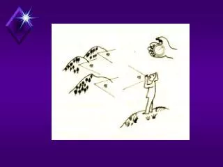
Linear Imaging Systems Image = object Point Spread Function + noise A convolution is a linear blurring. Every point in P is shifted, mapped and added to the output corresponding to the shape of O.
Linear Imaging Systems Consider the simple model, a plane of sources I(x,y) mapped onto a plane of detectors E(x,y). The detectors measure photon intensity (energy) and do so in a linear fashion (if twice the photon intensity impinges on the detector it returns a signal twice as large). Question: what would happen if the detectors saturated?
Linear Imaging Systems There is a mapping from the source to the detector, and the mapping is a linear functional so, a and b are scalars.
Linear Imaging Systems When we model the system as a linear functional then it is useful to introduce a point source and to decompose the system into these. The point source can select out every element of the input and follow how each element is mapped. The benefit is that by focusing on how the points map we don’t need to include the object function in our analysis of the imaging process.
The Delta Function The delta function allows a simple formal approach to the decomposition of the image. In 1 dimension, The delta function is thus a singularity and has the following convenient properties: It is normalized and can select out a point of a second function, provided f(x) is continuous in the neighborhood of x=0.
The Delta Function The delta function also allows sampling at frequencies other than x=0, So we can use the delta function to sample the object function anywhere in space.
The Delta Function It is useful to introduce some more physical representations of the delta function: Using these definitions you can show the various properties of the delta function.
The Delta Function in 2D The delta function is also straightforward to define in 2 dimensions, where The 2-dimensional delta function is therefore separable, We can also define the 2D delta function in cylindrical coordinates and this will be important for projection reconstruction, vida infra. are unit vectors.
Linear Imaging Systems Now that we have this useful construct of a delta function, let us return to our imaging system and decompose the plane of sources I(x,y). So any point in the source can be extracted as:
Linear Imaging Systems We know the output of that point, Now notice that E is a continuous function over the detector plane, and so I have labeled the function by the position in the source plane.
Linear Imaging Systems Now let us just explicitly write out the function: Since S and the integrations are all linear we can change their order. Now we see that the mapping is described for each point in the object function, and that the object function itself simply provides a weight for that point. Of course it is essential that S be linear.
Instrument Response Function Now we picture every point as being mapped onto the detector independently. The mapping is called the instrument response function (IRF).
Instrument Response Function The Instrument Response Function is a conditional mapping, the form of the map depends on the point that is being mapped. This is often given the symbol h(r|r’). Of course we want the entire output from the whole object function, and so we need to know the IRF at all points.
Space Invariance Now in addition to every point being mapped independently onto the detector, imaging that the form of the mapping does not vary over space (is independent of r0). Such a mapping is called isoplantic. For this case the instrument response function is not conditional. The Point Spread Function (PSF) is a spatially invariant approximation of the IRF.
Point Spread Function So now in terms of the Point Spread Function we see that the image is a convolution of the object function and the Point Spread Function. Here I have neglected noise, but in real systems we can not do that.
Magnification A system that magnifies initially looks like it should not be linear, but the mapping can also be written as a convolution. The IRF of course must include the magnification (M), and the image is,
Magnification A simple change of variables, Lets us rewrite the image as: And the imaging system is again correctly described as a convolution. We also directly see that as the image is magnified its intensity decreases.
An Example, the Pin-hole Camera One of the most familiar imaging devices is a pin-hole camera. The object is magnified and inverted. Magnification = -b/a Known prior to della Porta ca. 1600.
An Example, the Pin-hole Camera 2 Notice, however, that the object function is also blurred due to the finite width of the pin-hole. The extent of blurring is to multiply each element of the source by the “source magnification factor” of (a+b)/a x diameter of the pin-hole.
Distortions of a Pin-hole Camera Even as simple a device as the pin-hole camera has distortions 1. Limited field of view due to the finite thickness of the screen. As the object becomes too large, the ray approaches the pin-hole too steeply to make it through.
Distortions of a Pin-hole Camera 2 Also, as the object moves off the center line, the shadow on the detector grows in area, (and the solid angle is decreased) so the image intensity is reduced. There are three effects, radial distance cos^2, oblique angle cos, and effective size of pinhole cos. Therefore cos^4. The general oblique angle effect goes as cos^3.
Distortions of a Pin-hole Camera Reduction in field of view due to oblique angle effect. Cos^3 Cos^4
Contrast and Noise in a Pin-hole Camera For a screen of finite thickness some light will penetrate. Object function
Full 2D analysis Object function