Download
1 / 38
380 likes | 509 Views
GLAST - an Astro-Particle Mission to Explore the High Energy Gamma Ray Sky Alessandro Brez INFN - sez. Pisa. VERTEX 2003 Low Wood Lake Windermere, Cumbria, UK, September 14-19 2003. SUMMARY The GLAST mission, the detector and the science goals The tracker of GLAST

E N D
GLAST - an Astro-Particle Mission to Explore the High Energy Gamma Ray Sky Alessandro Brez INFN - sez. Pisa VERTEX 2003 Low Wood Lake Windermere, Cumbria, UK, September 14-19 2003
SUMMARY • The GLAST mission, the detector and the science goals • The tracker of GLAST • Status of the tracker construction and Engineering Model results
Profound Connection between Astrophysics & HEP The fundamental theory ofCosmic Genesis and the questfor experimental evidencehas led to new and potential partnerships between Astrophysics and HEP. • Some Areas of Collaboration: • Origin of cosmic rays • Dark Matter Searches • CMBR • Quantum gravity • Structure Formation • Early Universe Physics • Understanding the HE Universe • Typical signatures • Ultra HE cosmic rays • gamma-rays -> GLAST • n • antimatter • extensive use of high resolution and reliable particle detectors now possible after long and successful experience in particle physics
GLAST Concept Low profile for wide f.o.v. Segmented anti-shield to minimize self-veto at high E. Finely segment calorimeter for enhanced background rejection and shower leakage correction. High-efficiency, precise track detectors located close to the conversions foils to minimize multiple-scattering errors. Modular, redundant design. No consumables. Low power consumption (580 W) Charged particle anticoincidence shield Conversion foils Particle tracking detectors e+ e- • Calorimeter • (energy measurement) GLAST g detection technique – pair conversion telescope Pair production is the dominant photon interaction above 10MeV: E -> me+c2 + me-c2
Tracker Grid Thermal Blanket ACD DAQ Electronics Calorimeter GLAST Instrument: the Large Area Telescope (LAT) • Array of 16 identical “Tower” Modules, each with a tracker (Si strips) and a calorimeter (CsI with PIN diode readout) and DAQ module. • Surrounded by finely segmented ACD (plastic scintillator with PMT readout). • Aluminum strong-back “Grid,” with heat pipes for transport of heat to the instrument sides.
LAT Instrument Performance Including all Background & Track Quality Cuts
TheGLASTParticipating Institutions American Team Institutions SU - Stanford University, Physics Department and EGRET group, Hanson Experimental Physics Laboratory SU-SLACStanford Linear Accelerator Center, SLAC, Particle Astrophysics group GSFC-NASA Goddard Space Flight Center, Laboratory for High Energy Astrophysics NRL - U. S. Naval Research Laboratory, E. O. Hulburt Center for Space Research, X-ray and gamma-ray branches UCSC- University of California at Santa Cruz, Physics Department SSU- Sonoma State University, Department of Physics & Astronomy UW- University of Washington , TAMUK- Texas A&M University-Kingsville Italian Team Institutions INFN - Instituto Nazionale di Fisica Nucleare: Units of Bari, Perugia, Pisa, Rome 2, Tries ASI - Italian Space Agency IFC/CNR- Istituto di Fisica, Cosmica, CNR Japanese Team Institutions University of Tokyo ICRR - Institute for Cosmic-Ray Research ISAS- Institute for Space and Astronautical Science Hiroshima University French Team Institutions CEA/DAPNIA Commissariat à l'Energie Atomique, Département d'Astrophysique, de physique des Particules, de physique Nucliaire et de l'Instrumentation Associée, CEA, Saclay IN2P3 Institut National de Physique Nucléaire et de Physique des Particules, IN2P3 IN2P3/LPNHE-X Laboratoire de Physique Nucléaire des Hautes Energies de l'École Polytechnique IN2P3/PCC Laboratoire de Physique Corpusculaire et Cosmologie, Collège de France IN2P3/CENBG Centre d'études nucléaires de Bordeaux Gradignan Swedish Team Institutions KTHRoyal Institute of Technology Stockholms Universitet
0.01 GeV 0.1 GeV 1 GeV 10 GeV 100 GeV 1 TeV Active Galactic Nuclei Solar flares Unidentified sources Cosmic ray acceleration Pulsars Dark matter Gamma Ray Bursts GLAST science - the sky above 100 MeV
Broad spectral coverage is crucial for studying and understanding most astrophysical sources. GLAST and ground-based experiments cover complimentary energy ranges. The improved sensitivity of GLAST is necessary for matching the sensitivity of the next generation of ground-based detectors. GLAST goes a long ways toward filling in the energy gap between space-based and ground-based detectors—there will be overlap for the brighter sources. Covering the Gamma-Ray Spectrum Predicted sensitivities to a point source. EGRET, GLAST, and Milagro: 1-yr survey. Cherenkov telescopes: 50 hours on source. (Weekes et al., 1996, with GLAST added)
Identifying Sources GLAST 95% C.L. radius on a 5 source, compared with a similar EGRET observation of 3EG 1911-2000 Unidentified Sources Counting stats not included. 170/271 3rd EGRET catalog still unidentified GLAST high resolution and sensitivity will • resolve gamma-ray point sources at arc-minute level • detect typical signatures (e.g. spectra, flares, pulsation) for identification with known source types Cygnus region (150 x 150), Eg > 1 GeV
Halo WIMP annihilations X q gg or Zg q lines ~ X Example: X is c0 from Standard SUSY, annihilations to jets, producing an extra component of multi-GeV g flux that follows halo density (not isotropic) peaking at ~ 0.1 Mc0 or lines at Mc0. Background is galactic g ray diffuse. ~ ~ Good particle physics candidate for galactic halo dark matter is the LSP in R-parity conserving SUSY If true, there may well be observable halo annihilations If SUSY uncovered at accelerators, GLAST may be able to determine its cosmological significance quickly.
g lines 50 GeV 300 GeV Supersymmetric Cold Dark Matter searches with GLAST Total photon spectrum from galactic centre with cc annihilation contribution infinite energy resolution finite energy resolution 2-year scanning mode Bergstrom et al.
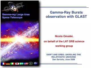
Simulated one-year GLAST scan, assuming a various spectral indexes. 1- localization accuracy (arc min.) Gamma-Ray Bursts • GLAST LAT will be best suited to studying the GeV tail of the gamma-ray burst spectrum. A separate instrument (GBM) on the spacecraft will cover the energy range 10 KeV – 25 MeV and will provide a hard X-ray trigger for GRB. • GLAST should detect 200 GRB per yearwith E>100 MeV, with a third of them localized to better than 10, in real time. • Excellent wide field monitor for GRB.Nearly real-time trigger for other wavelength bands, often with sufficient localization for optical follow-up. • With a 10s dead time, GLAST will see nearly all of the high-E photons. GBM LAT Energy dependent lags and the physics behind GRB temporal properties will be better studied by the broad energy coverage (10 KeV – 100 GeV) provided by GBM and LAT.
Gamma-Ray Bursts • transient signal, ~ 100 µs time scale • light curves vs energy • fast response/ short dead time spectral studies for • non-thermal emission model (synchrotron, ICS) • fireball baryon fraction • high energy resolution Simulated time profile of a GRB detected by the LAT and the GBM. The pulses are narrower at LAT energies. • The origin of ultra-energy cosmic rays suggested to be GRBs (Waxman 1995) • Burst of high energy g as signature of the evaporation of primordial black holes.
Multi-Chip Electronics Module (MCM) 19 Carbon-Fiber Tray Panels Carbon-Fiber Sidewalls (Aluminum covered) 2 mm gap Readout Cable Titanium Flexure Mounts GLAST Tracker Design Overview • 16 “tower” modules, each with 37cm 37cm of active cross section • 83m2 of Si in all, like ATLAS • 11500 SSD, ~ 1M channels • 18 x,y planes per tower • 19 “tray” structures • 12 with 3% W on bottom (“Front”) • 4 with 18% W on bottom (“Back”) – • 3 with no converter foils • Every other tray is rotated by 90°, so each W foil is followed immediately by an x,y plane of detectors • 2mm gap between x and y oriented detectors • Trays stack and align at their corners • The bottom tray has a flange to mount on the grid. • Electronics on sides of trays: • Minimize gap between towers • 9 readout modules on each of 4 sides
Tracker Production Overview Module Structure Components SLAC: Ti parts, thermal straps, fasteners. Italy (Plyform): Sidewalls SSD Procurement, Testing SLAC,Japan, Italy (HPK) SSD Ladder Assembly Italy (G&A, Mipot) 10,368 Tracker Module Assembly and Test Italy (Alenia Spazio) 2592 18 Tray Assembly and Test Italy (G&A) 342 342 Electronics Fabrication, burn-in, & Test UCSC, SLAC (Teledyne) 648 Composite Panel, Converters, and Bias Circuits Italy (Plyform): fabrication SLAC: CC, bias circuits, thick W, Al cores Readout Cables UCSC, SLAC (Parlex)
SSD Electrical Test Rate SSD in Italy 9452 (82% of total, enough for 16 towers) SSD tested 7373 (64% of total) SSD to review 201 SSD rejected 44 Cumulative test rate
SSD Electrical Properties Specification: leakage current <500 nA at 25C and 150 V
Ladder Assembly Encapsulated bondings Ladder assembly tool Manual fast AND precise method 24 ladder assembly tools used in parallel Very good ladder alignment obtained
Ladders Electrical Tests • Electrical test results: • Ladder tested 513 • Accepted 501(98%) • Broken edge 6 • High current 6 • (>2mA@150V) • The cause of problem 3 has been corrected.
Ladders Electrical Tests Leakage current at 150 V Depletion voltage
Tray Panel Fabrication • Machining of the Carbon-Carbon closeout material is just starting. • Face sheets, cores, inserts, and tungsten are in hand. • Bias circuits are out for quote. • PRR actions are being closed. Gr/CE Face Sheet C-C Structural Closeout Wall Thermal Boss 1 lb/ft3 Aluminum Honeycomb Core C-C MCM Closeout Wall
Tracker Tray with Payload • The tray “payload” is bonded to the sandwich structure using epoxy, with the exception of the SSD bonding, which is done with silicone. • Silicone decouples the thermal/mechanical effects from the tray
Vibrational test Sine sweep before/after random Random vibration + White noise Z accelerometer response X accelerometer response Y accelerometer response TG07 TG07 Resonance search: 0= 815 Hz, Q 51 Resonance check: 0= 809 Hz, Q 49 All the EM trays have been successfully tested at qualification level. No damages or relevant frequency shifts have been observed
Bare Panel: N.D.I. Test ESPI: Thermal Loads very effective to detect bare panel defects Skin-closeout debonding Honeycomb crash Honeycomb – Skin debonding
ESPI: Vibration TEST TG07: Bare Panel + W + Bias Plane 817Hz first resonance mode 1860Hz second resonance mode
Ladder assembly on the trays Ladder positioning Tray positioning Microbonding Assembly phases
Ladder alignment results measurement points s=28mm MCM side 0.2mm y x s=46mm s=32mm
Tray box The tray box allows safe shipping and storage. Through the connector savers the tray can be fully tested in the closed box. Fixation points Handle Connector saver N2 inlet
Trays Thermal qualification cycles DL/L (me) Temperature (°C) • Qualification-like test: • temperature range: -30°C +50°C • T0=24°C • numberof cycles: 4 • 2 hr @ -30 °C, +50 °C • (dT/dt)= 0.5 °C/min T=25 °C: L/L 100 T=-55 °C: L/L - 350 Thermal test lot ≥ 4 trays/cycle in 4 climatic chambers (2 ready by Pg in Terni, 1 foreseen in Pi, 1 foreseen in Ba) Test rate/climatic chamber ∼ 1 tower/month
Assembly of EM Tower in G&A Trays alignment onassembly jig Cabling Geometrical tolerances well within limits (0.3 mm).
Mini-Tower Assembly & Test Mini-tower concept: 3 XY working planes for detection capability test (Aluminum grid fixture is removed)
Cosmic Rays – Online DATA The trigger occurs when particles traverse the 6 consecutive layers of the MiniTower.
Occupancy @ beginning of efficiency plateau is already as low as 10 –7 (mainly cosmics) Occupancy @ DAC Threshold = 10 Detection efficiency Full efficiency plateau up to ½ MIP 60% 1MIP
layer Ratio Exp STDEV (um) Expected value Meas STDEV (um) Measured value Meas AVG (um) X1 mean(X2)/mean(X1) 250 0.46 225 0.46 -185 X2 mean(X2)/mean(X3) 115 0.54 105 0.53 85 mean(Y2)/mean(Y1) X3 210 0.54 195 0.55 -160 mean(Y2)/mean(Y3) Y1 210 0.46 240 0.48 -64 Y2 115 135 35 Y3 250 275 -75 Spatial resolution Alignment
Integration of MiniTKR and CAL at SLAC Courtesy of I&T team
conclusions GLAST construction is going on with very good results. The close combined effort of HEP Institutes with high tech companies lead to a fast, precise, high yield production. The HEP Institutes have defined the project and will conduct the test activity. The industrial counterpart is essential in defining the more technological details, provides the specialized manpower, assure the Quality certification of the production.