Download
1 / 45
450 likes | 551 Views
Explore the electromagnetics of superconductors, residual resistance, and surface impedance in RF cavities for particle acceleration applications.

E N D
CAS April-May 2013 Erice, Italy AC/RF SUPERCONDUCTIVITY GianluigiCiovati Thomas Jefferson National Accelerator Facility Newport News, Virginia, USA
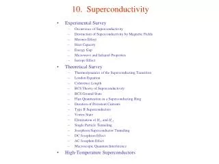
Outline • Introduction to RF Cavities • Electrodynamics of normal-conductors • Electrodynamics of superconductors • Surface impedance • Two-fluid model and BCS theory • Residual resistance • Superheating field • Field dependence of the surface resistance due to thermal feedback
RF Cavities • Devices that store e.m. energy and transfer it to a charged particle beam • E.m.field in the cavity is solution to the wave equation H • Solutions are two family of modes with different eigenfrequencies • TEmnp modes have only transverse electric fields • TMmnp modes have only transverse magnetic fields (but longitudinal component for E) E • Accelerating mode: TM010 H f L = bcTRF/2 E1 E2 z E q q r Example: 2 GHz cavity and speed of light e- L = 7.5 cm, R = 5.7 cm
Figures of merit (1) • What is the energy gained by the particle? • Let’s assume a relativistic e- • Integrate the E-field at the particle position as it traverses the cavity • We can define the accelerating field as: • Important for the cavity performance are the ratios of the peak surface fields to the Eacc. Ideally, these should be small to limit losses and other troubles at high fields
Figures of merit (2) • The power dissipated in the cavity wall due to Joule heating is given by: • The energy stored in the cavity is given by: • The cavity quality factor is defined as: dv Dw = G 0
SRF cavity performance Rs 8 nW Bp 185 mT T=2.0 K f = 1.3 GHz F. Furuta et al., Proc. EPAC’06, p. 750
Surface Impedance • The electromagnetic response of a metal, whether normal or superconducting, is described by a complex surface impedance: surface reactance surface resistance For a good conductor and w < ~1016 Hz • The impedance of vacuum is: For accelerator applications, the rate of oscillation of the e.m. field falls in the radio-frequency (RF) range (3 kHz – 300 GHz)
Electrodynamics of normal conductors • From Drude’s model (“nearly free electrons”): (linear and isotropic) material’s equations Maxwell’s equations t = l/vF 10-14 s is the electrons’ scattering time Ohm’s law, local relation between J and E s wt << 1 at RF frequencies
Surface impedance of normal conductors • From previous slide you obtain: • Solution (semi-infinite slab): Ez(x,t) skin depth: Hy(x,t) z y x Example: Cu at 1.5 GHz, 300 K (s = 5.8107 1/Wm, m0=1.2610-6 Vs/Am, m=1) d = 1.7 mm, Rs = 10 mW
What happens at low temperature? • s(T) increases, d decreases The skin depth (the distance over which fields vary) can become less than the mean free path of the electrons (the distance they travel before being scattered) • Introduce a new relationship where J is related to E over a volume of the size of the mean free path (l) Effective conductivity = t Contrary to the DC case higher purity (longer l) does not increase the conductivity anomalous skin effect
So, how good is Cu at low T? “Extreme” anomalous limit (OK for Cu in RF and low T) for Cu Does not compensate for the refrigerator efficiency!!!
Superconductivity - remainder The 3 Hallmarks of Superconductivity
London equations - remainder • E=0: Js goes on forever • E is required to maintain an AC current • B is the source of Js • Spontaneus flux exclusion
Bad news: Rs > 0 • In AC fields, the time-dependent magnetic field in the penetration depth will generate an electric field: • Because Cooper pairs have inertia (mass=2me) they cannot completely shield nc electrons from this E-field Rs > 0 So, how does Rs for a superconductor compare to that of a normal conductor?
Two-fluid model • Gorter and Casimir (1934) two-fluid model: charge carriers are divided in two subsystems, superconducting carriers of density ns and normal electrons of density nn. • The superconducting carriers are the Cooper pairs (1956) with charge -2e and mass 2m • The normal current Jn and the supercurrentJs are assumed to flow in parallel. Js flows with no resistance. Vacuum SC J = Jn + Js H0
Electrodynamics of superconductors (at low field) • London equations: London penetration depth • Currents and magnetic fields in superconductors can exist only within a layer of thickness lL Note: Local condition between current and field. Valid if x0 << lL or l << lL
Surface impedance of superconductors • Electrodynamics of sc is the same as nc, only that we have to change s s1 – is2 = s2 s • Penetration depth: s1 << s2 for sc at T<<Tc For Nb, lL = 36 nm, compared to d = 1.7 mm for Cu at 1.5 GHz
Surface impedance of superconductors For a sc s1 << s2 y <<1 Ls: kinetic inductance
Surface resistance of superconductor • Rs s1 l longer m.f.p (higher conductivity) of unpaired e- results in higher Rs ! • Rs w2 use low-frequency cavities to reduce power dissipation • Temperature dependence: ns(T) 1-(T/Tc)4 s1(T) nn(T) e-D/kBT Unpaired electrons are created by the thermal breakup of Cooper pairs T < Tc/2
Material purity dependence of Rs • If x0 >> lL and l >> lL, the local relation between current and field is not valid anymore (similarly to anomalous skin effect in normal conductors) Pippard (1953): • The dependence of the penetration depth on l is approximated as if l >> x0 (“clean” limit) if l << x0 (“dirty” limit) Rs has a minimum for l = x0/2
BCS surface resistance (1) • From BCS theory of sc, Mattis and Bardeen (1958) have derived a non-local equation between the total current density J and the vector potential A can be converted in a product in Fourier domain: J(q) = -K(q)A(q) • The surface impedance can be derived in term of the Kernel K(q): for diffuse scattering of electrons at the metal surface
BCS surface resistance (2) • There are numerical codes (Halbritter (1970)) to calculate RBCS as a function of w, T and material parameters (x0, lL, Tc, D, l) • For example, check http://www.lepp.cornell.edu/~liepe/webpage/researchsrimp.html • A good approximation of RBCS for T < Tc/2 and w < D/ħ is: • RBCS C1 = 2.246 Let’s run some numbers: Nb at 2.0 K, 1.5 GHz l = 40 nm, sn = 3.3108 1/Wm, D/kBTc = 1.85, Tc = 9.25 K RBCS 20 nW Xs 0.47 mW Nb Cu
Time to celebrate ! Not so fast… • Refrigeration isn’t free: Carnot efficiency: hC= 2 K/(300 K – 2 K) = 0.007 Technical efficiency of cryoplant: hT 0.2 Total efficiency: htot 0.0014 1/700 Power reduction from Cu(300K) to Nb(2K) is 103
Experimental results Frequency dependence Dependence on material purity • Small deviations from BCS theory can be explained by strong coupling effects, anisotropic energy gap in the presence of impurity scattering or by inhomogeneities Nb,1.5 GHz, 4.2 K C. Benvenuti et al., Physica C 316 (1999) 153. “clean” “dirty” Nb, 4.2 K • Nb films sputtered on Cu • By changing the sputtering species, the mean free path was varied A. Phillip and J. Halbritter, IEEE Trans. Magn. 19(3) (1983) 999. RBCS can be optimized by tuning the density of impurities at the cavity surface.
Residual resistance Possible contributions to Rres: • Trapped magnetic field • Normal conducting precipitates • Grain boundaries • Interface losses • Subgap states B. Aune et al., Phys. Rev. STAB 3 (2000) 092001. Rs = RBCS(w, T, D, Tc, lL, x0, l) + Rres(?) Nb, 1.3 GHz 2 K For Nb, Rres (~1-10 nW) dominates Rs at low frequency (f < ~750 MHz) and low temperature (T < ~2.1 K)
Possible contributions to Rres in Nb (1) • Trapped magnetic field In technical materials, the Meissner effect is incomplete when cooling below Tc in the presence of a residual magnetic field due to pinning Fluxoids: normal conducting core of area ~px02 and normal-state surface resistance, Rn if 100% flux pinning Rres due to Earth’s field (~500 mG) at 1.5 GHz: ~120 nW (~6RBCS(2K)) Apply magnetic shielding around cavities
Possible contributions to Rres in Nb (1) • Trapped magnetic field Including the oscillatory motion of a fluxoid due to the Lorentz force: In the frequency limit where only the tip of the fluxoid vibrates: Anisotropy parameter w2 A. Gurevich and G. Ciovati, Phys. Rev. B. 87, 054502 (2013) For Nb: rn~510-10Wm, Hc=2000 Oe, 2g=1
Possible contributions to Rres in Nb (2) • Normal conducting precipitates If the bulk H content in high-purity (RRR~300) Nb is > ~5 wt.ppm, precipitation of normal-conducting NbHx islands occurs at the surface if the cooldown rate is < ~1 K/min in the region 75-150 K Nb cavities are heat treated at 600 – 800 °C in a UHV furnace to degas H B. Aune et al., Proc. 1990 LINAC Conf. (1990) 253.
Possible contributions to Rres in Nb (3) • Grain boundaries • Interface losses Results are still inconclusive • Subgap states Results are still inconclusive Tunneling measurements show that the BCS singularity in the electronic density of states is smeared out and subgap states with finite N(e) appear at energies below ∆. BCS Phenomenological formula [Dynes (1978)]: g: damping parameter Finite density of states at the Fermi level: subgap states Residual resistance (s1 sng/D): Rres ~10 nWat 1.5 GHz for g/D = 10-3 A. Gurevich, Rev. Accel. Sci. Tech. 5, 119 (2012)
About HTS… HTS LTS • HTS materials have nodes in the energy gap. This leads to power-law behavior of λ(T) and Rs(T) and high residual losses • x ~ 1 – 2 nm (<< l) superconducting pairing is easily disrupted by defects (cracks, grain boundaries) • “Granular” superconductors: high grain boundary resistance contributing to Rres YBCO We are stuck with LHe! Hein M A 1996 Studies in High Temperature Superconductors vol 18 ed A Narlikar (Nova Science Publishers) pp 141–216
Surface barrier How do vortices get in a superconductor? • Meissner currents push the vortex in the bulk • Attraction to the antivortex image pushes the vortex out Two forces acting on the vortex at the surface: Thermodynamic potential G(b) as a function of the position b: • Vortices have to overcome the surface barrier even at H > Hc1 • Surface barrier disappears only at H=Hsh • Surface barrier is reduced by defects Hsh
What is the highest RF field applicable to a superconductor? Type-II SC • Penetration and oscillation of vortices under the RF field gives rise to strong dissipation and the surface resistance of the order of Rs in the normal state • the Meissner state can remain metastable at higher fields, H > Hc1up to the superheating fieldHshatwhich the Bean-Livingston surface barrier for penetration of vortices disappears and the Meissner state becomes unstable Normal State Hsh(0) H Hc2(0) Hshis the maximum magnetic field at which a type-II superconductor can remain in a true non-dissipative state not altered by dissipative motion of vortices. Abrikosov Vortex Lattice Hc1(0) Meissner State At H = Hsh the screening surface current reaches the depairing value Jd = nseD/pF Tc T
Superheating field: theory • Calculation of Hsh(k) from Ginzburg-Landau theory (TTc) [Matricon and Saint-James (1967) ]: Time evolution of the spatial pattern of the order parameter in a small region around the boundary where a vortex entrance is taking place, calculated from time-dependent GL-equations. t A. D. Hernandez and D. Dominguez, Phys. Rev. B 65, 144529 (2002) H. Padamsee et al., RF Superconductivity for Accelerators (Wiley&Sons, 1998)
Superheating field: theory • Calculation of Hsh(T, l) for k >> 1 from Eilenberger equations (0<T<Tc) [Pei-Jen Lin and Gurevich (2012)]: • Weak dependence of Hsh on non-magnetic impurities a = px0/l Impurity scattering parameter F. Pei-Jen Lin and A. Gurevich, Phys. Rev. B 85, 054513 (2012)
Superheating field: experimental results • Use high-power (~1 MW) and short (~100 ms) RF pulses to achieve the metastable state before other loss mechanisms kick-in Highest Hp ever measured in CW!!! Nb Hc1 Nb3Sn Hc1 T. Hays and H. Padamsee, Proc. 1997 SRF Workshop, AbanoTerme, Italy, p. 789 (1997) . • RF magnetic fields higher than Hc1 have been measured in both Nb and Nb3Sn cavities. However max HRF in Nb3Sn is << predicted Hsh…
However… • In “real” surfaces, the surface barrier can be easily suppressed locally by “defects” such as roughness or impurities, so that vortices may enter the sc already at HRF Hc1 1.5 GHz, Nb3Sn film deposited on Nb G. Muller et al., Proc. 1996 EPAC, Spain, p. 2085 (1996) Hp 30 mT ~ Hc1
Multilayer Films • If Hc1 is indeed a major practical limit for RF application of high-k materials, a possible solution consists of S-I-S multilayers [Gurevich (2006)]: Suppression of vortex penetration due to the enhancement of Hc1 in a thin film with d < [Abrikosov, (1964)] Higher-TcSC: NbN, Nb3Sn, etc Nb Ha = exp(-Nd/l) Insulating layers A. Gurevich, Appl. Phys. Lett. 88, 012511 (2006)
Alternatives to Nb • Global surface resistance: Example: 4 layers 30 nm thick of Nb3Sn on Nb Ha up to ~400 mT [~Hsh(Nb3Sn)] with Hi ~ 100 mT << Hsh(Nb) R0Nb3Sn(2 K) 0.1 RbNb(2 K) Rs 0.15 Rb
Global thermal instability • The exponential temperature dependence of Rs(T) provides a strong positive feedback between RF Joule power and heat transport to the coolant thermal instability above the breakdown field Hb k: thermal conductivity hK: Kapitza conductance Tm-T0<<T0 = a, total thermal conductance A. Gurevich, Physica C 441, 38 (2006)
Uniform thermal breakdown field Hb = max H0(Tm) = H0(Tb) Tb-T0 T02/DTc= 0.23 K for Nb Rres 0 m0H0 (mT) exp(-DTc/Tb) exp(-DTc/T0+1) Rres = 0 Rres = 0.5 RBCS Tb d = 3 mm f = 1.5 GHz RBCS(2 K) = 20 nW hK = 5 kW/m2 K k = 10 W/m K T0 = 2 K D/k = 17.1 K Tm (K)
Uniform thermal breakdown field Nb, 2 K, same parameters as previous slide • Higher frequencies not only reduce the cavity Q0 ( Rs) but also the breakdown field Bsh m0Hb (mT) For 1.5 mm thick Nb on 3 mm thick Copper (hK,Cu=8.4 kW/m2 K, kCu=200 W/m K) f (GHz) In case of multilayers the thermal conductance is: Nb3Sn coating with Nds = 100 nm, s = 10-2 W/m K Insulating Al2O3 layers, Ndi = 10 nm, i= 0.3 W/m K di/i = 1/300(ds/s) Insulating layers are negligible d/= 3Nds/s TFML adds ~30% to the thermal resistance of the Nb shell
Q0(B0) curve • Because of the Tm(H0) dependence, Rs acquires a H0-dependence Surface treatments Nb, 2 K, 1.5 GHz, G=280 W,Rs and thermal parameters as in previous slides Q0 Intrinsic non-linearities B0(mT)
Summary • Unlike in the DC case, dissipation occurs in SC in RF because of the inertia of Cooper-pairs • The surface resistance can be easily understood in terms of a two-fluid model and is due to the interaction of the E-field (decaying from the surface) with thermally excited normal electrons • Rs = RBCS + Rres • The maximum theoretical RF field on the surface of a SC is the superheating field thermodynamic critical field • Multilayer films may be a practical way to reach Hsh in SC with higher Tc than Nb • Thermal feedback couples Rs at low field to the breakdown field • Residual DC magnetic field • Normal-conducting precipitates (NbH) • … • Increases quadratically with frequency • Decreases exponentially with temperature • Has a minimum as a function of material purity
Acknowledgments & References • Inspiration and material for this lecture was taken from earlier ones from: Prof. A. Gurevich, ODU; Prof. Steven M. Anlage, UMD; Prof. J. Knobloch, BESSY; Prof. H. Padamsee, Cornell U. • Tutorials on SRF can be found on the webpages of SRF Workshops: http://accelconf.web.cern.ch/accelconf/ • Recommended references: • M. Tinkham, Introduction to Superconductivity, McGraw-Hill, New York, 2nd edition, 1996 • H. Padamsee, J. Knobloch and T. Hays, RF Superconductivity for Accelerators, J. Wiley & Sons, New York, 1998 • H. Padamsee, RF Superconductivity. Science, Technology, and Applications, Wiley-VCH, Weinheim, 2009 • A. Gurevich, “Superconducting Radio-Frequency Fundamentals for Particle Accelerators”, Rev. Accel. Sci. Tech. 5, 119 (2012)