Download
1 / 27
270 likes | 285 Views
This article discusses the detection requirements for forward processes recoils in deep-exclusive (diffractive) processes. It covers the necessary equipment and techniques to detect recoiling heavy ions and achieve good acceptance at small pT for extending the mass range.

E N D
Detection requirements for forward processes Recoils in deep-exclusive (diffractive) processes • Large t (pT) range desirable • Small t: needs Roman pots to go close to the beam • Large t: needs large acceptance magnets • Coherent nuclear processes • Recoiling heavy ions are very difficult to detect • Good acceptance at small pT extends the mass range Partonic fragmentation in SIDIS • Also decays of strange and charmed baryons Nuclear fragments • Measure complete final state (all fragments) in heavy-ion reactions • Centrality of collision (shadowing, saturation, hadronization, etc) • Spectator tagging with polarized light ions • Our LDRD!
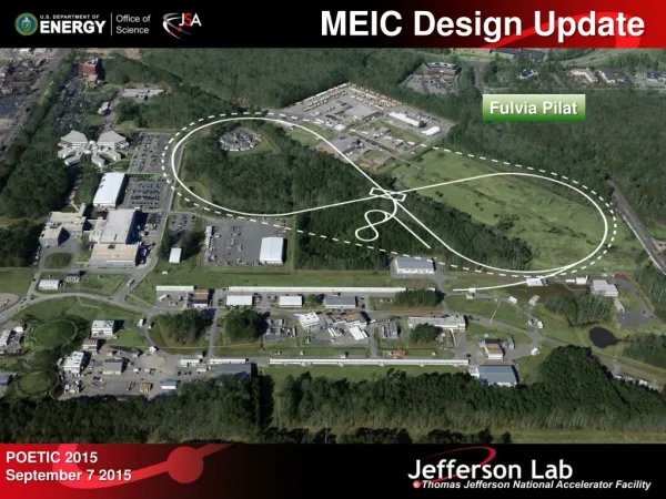
The EIC at Jefferson Lab • 12 GeV CEBAF is a full-energy e-injector • Continuous injection as at SLAC (~50 nA) • Parallel running with fixed target possible e injection Hall D MEIC • Both the MEIC and CEBAF have a 1.4 km circumference Ion linac Pre-booster IP1 C E B A F • MEIC can store 20-100 GeV protons, or heavy ions up to 40 GeV/A. IP2 High-Energy Arc (Stage II) • The stage II EIC will increase the energy to 250 GeV for protons and 20 GeV for electrons. Halls A-C • Two high-luminosity, full-acceptance detectors • IP2 could host sPHENIX
EIC MEIC MEIC (arXiv:1209.0757) MEIC – specific design goals Spin control for all light ions • Figure-8 layout • Vector- and tensor polarized deuterium Stable concept – detailed design report released August 2012 Full-acceptance detector • Ring designed around detector requirements • Detection of all fragments – nuclear and partonic Minimized technical risk
MEIC accelerator parameters * Includes space-charge effects and assumes conventional electron cooling Red indicates parameters specific to the full-acceptance detector
Dechirper Rechirper Conventional electron cooling using a 55 MeV ERL • Conventional electron cooling is a well- established technique (e.g. at Fermilab) • A single-pass Energy-Recovery Linac (ERL) allows reaching higher electron energies and currents • A recirculator ring is not needed for the ready-to-build MEIC cooling scheme, but would reduce source current requirements • Recirculator tests are planned at the JLab Free-Electron Laser (FEL) ERL Cooler Test Facility @ JLab FEL ERL
Science program demands highly polarized (>70%) light ions (p, D, 3He, Li, ...) Figure-8 shape used for all ion booster and collider rings Spin precession in one arc is canceled by the other arc No preferred periodic spin direction Energy-independent spin tune Simplified polarization control and preservation for all ion species Needs only small magnetic fields (instead of Siberian Snakes) to control polarization at Ips The electron ring has a figure-8 shape because it shares a tunnel with the ion ring Figure-8 ring is the only practical way to accelerate polarized deuterons Pre-Booster MEIC – ion polarization in figure-8 ring Large booster Ion Collider Ring
The MEIC detector locations (in CAD) • Detector locations minimize synchrotron- and hadronic backgrounds • Close to arc where ions exit • Far from arc where electrons exit The background is an artist's impression • The MEIC magnetic lattice design is complete
The MEIC full-acceptance detector concept Forward hadron detection in three stages: 1. Endcapwith 50 mradcrossing angle 2. Small dipolecoveringanglesupto a fewdegrees 3. Far-forward, uptoonedegree, forparticlespassingtheacceleratorquads (from GEANT4) small angle hadron detection IP FP far forward hadron detection n, g low-Q2 electron detection e ion quads large-aperture electron quads ~60 mrad bend small-diameter electron quads 50 mrad beam (crab) crossing angle p Fixed trackers in vacuum? Thin exit windows Roman pots central detector with endcaps 1 m Ion quadrupoles 1 m Endcap dual-solenoid in common cryostat 4 m coil 2 Tm dipole Electron quadrupoles RICH + TORCH? barrel DIRC + TOF Trackers and “donut” calorimeter e/π threshold Cherenkov EM calorimeter Tracking EM calorimeter EM calorimeter
Central detector options dual-solenoid in common cryostat 4 m coil Coil wall Coil wall RICH + TORCH? EM calorimeter e/π threshold Cherenkov EM calorimeter barrel DIRC + TOF forward tracker forward tracker 3 m Si-pixel vertex + disks central tracker • First TOSCA model of 3T dual solenoid. • Inspired by ILC 4th concept detector 1 m deep 2 m deep EM calorimeter (top view) 3 m 5 m • Goal: two sufficiently different, complementary central detectors • No need to for beam sharing at a ring-ring collider! • IP1 (shown above): new 3T dual solenoid and large tracker • Si-pixel disks and micropattern gas detector (GEM/micromega) forward trackers • Low-mass cluster-counting He-filled DC, and/or micropattern central tracker • IP2 can be instrumented using an old magnet (CLEO or BaBar) • Focus on hadronic calorimetry + small TPC central tracker
The MEIC IP2 could host sPHENIX • The planned PHENIX upgrade is based on the BaBar solenoid • Staged implementation denoted by various prefixes (s/fs/e) • Physics focus is jet physics using hadroniccalorimetry • Could also provide muon identification • A specific IR design for PHENIX@MEIC is in preparation
The low-Q2 tagger – small angle electron detection e- x • High-resolution detection of low-Q2 electrons using dipole chicane. e- ions (top view) ions low-Q2 tagger Electron beam aligned with solenoid axis e- final focusing elements
Crossing angle Hadron detection between endcap and ion quads 7 m from IP to first ion quad Ion quadrupoles: gradient, peak field, length 36 T/m, 7.0 T, 1.2 m 51 T/m, 9.0 T, 2.4 m 89 T/m, 9.0 T, 1.2 m 1 m 1 m Endcap detectors 2 T dipole Permanent magnets e Electron quadrupoles 2 x 15 T/m 34 T/m 46 T/m 38 T/m Tracking Calorimetry 5 T, 4 m dipole • Large crossing angle (50 mrad) • Moves spot of poor resolution along solenoid axis into the periphery • Minimizes shadow from electron FFQs • Dipole before quadrupoles further improves resolution in the few-degree range • Low-gradient quadrupoles allow large apertures for detection of all ion fragments • Peak field = quad gradient x aperture radius
Detection after the ion quads (n, γ) ZDC Aperture-free drift space 20 Tm dipole (in) 2 Tm dipole (out) p solenoid e S-shaped dipole configuration optimizes acceptance for neutrals Thin exit windows Roman pots at focal point 50 mrad crossing angle • S-shaped transport optimizes acceptance for both neutrals and charged particles. • Lots of space for Zero-Degree Calorimeter (ZDC) on the outside of the ring • Hcal and EMcal ions • ZDC Hcal: RD52 „DREAM“ or particle flow type.
Ultra-forward hadron detection – requirements 1. Good acceptance for ion fragments (rigidity different from beam) • Large downstream magnet apertures • Small downstream magnet gradients (realistic peak fields) • Roman pots not needed 2. Good acceptance for low-pT recoil baryons (rigidity similar to beam) • Small beam size at second focus (to get close to the beam) • Large dispersion (to separate scattered particles from the beam) • Roman pots important DVCS on the proton 3. Good momentum- and angular resolution • Large dispersion (but with D = D' = 0 at IP) • Long, instrumented, magnet-free drift space 4. Sufficient separation between beam lines (~1 m)
Asymmetric ion optics x Ions • β* x/y asymmetry allows a high luminosity with relatively small βmax βFP < 1 m βx*= 10 cm DFP ~ 1 m βy*= 2 cm D* = D'* = 0 IP FP • 7 m from IP to first downstream ion quad • Only dispersion component (D) generated after the IP aids detection, but any dispersion slope (D') at IP adds to the beam angular spread (Dp/p) • Beam angular spread is also proportional to √(ε/β*) → good ion beam cooling essential
Far-forward detection of charged fragments (protons rich fragments) (neutron rich fragments) Δp/p = -0.5 Δp/p = 0.0 Δp/p = 0.5 (spectator protons from deuterium) (exclusive / diffractive recoil protons) (tritons from N=Z nuclei) • For light ions focus the mass/charge ratio of fragments is usually very different from the beam • For heavy ions one needs both good acceptance and momentum resolution
50 mr crossing angle in ion beam Fragment acceptance vs quadrupole peak field Forward acceptance vs.magnetic rigidity horizontal plane vertical plane 6 T max accetance (degrees) Red: Detection before ion quadrupoles Blue: Detection after ion quadrupoles • Q3P can be weaker • “9 T” is actually 9, 9, and 7 Tesla 9 T max magnetic rigidity relative to beam • The angle is the original scattering angle at the IP
Fragment angular acceptance past the large dipole Quad apertures in 9, 9, 7 T (@ 100 GeV/c) configuration, dipole aperture = -30/+50 40 cm Uniform distribution of 1 in x and y angles around proton beam at IP for a set of p/p The circle indicates neutrals’ cone electron beam electron beam p/p = 0.5 p/p = -0.5 neutrons p/p = 0
Ion acceptance and resolution at the focal point ±10σ beam size at 60 GeV • Large deflections allow precise tracking over long distances with cheaper detectors • Particles with deflections > 1 m at the FP will be detected closer to the dipole • Detection past the focal point is also possible, but with acceptance restrictions
Far-forward hadron detection summary • Neutrals detected in a 25 mrad (total) cone down to zero degrees • Space for large (> 1 m diameter) Hcal + Emcal • Excellent acceptance for all ion fragments • Recoil baryon acceptance: • up to 99.5% of beam energy for all angles • down to at least 2-3 mrad for all momenta • full acceptance for x > 0.005 • Resolution limited only by beam • Longitudinal (dp/p): 3x10⁻⁴ • Angular (all φ): 0.2 mrad n, γ 20 Tm dipole p 2 Tm dipole solenoid e • 15 MeV/c resolution for a 50 GeV/A tagged deuteron beam
Momentum & Angular Resolution |x| > 3 mrad @ p/p = 0 ±10 @ 60 GeV/c electron beam electron beam
9 T max 6 T max 12 T max electron beam Far-Forward Acceptance for Neutrals
Lost or Extracted P0 (>Pt) Pt Electron polarization – continuous injection Equilibrium Polarization vs. Average Injected Current • Polarization at t+Δt • Equilibrium Polarization • Note that: • Polarization lifetime at 5 GeV is 1 or 3 hours depending on helicity (Sokolov-Ternov) • 50-100 nA beam injected from CEBAF can maintain polarization close to its initial value of 80% indefinitely for any elevtron beam energy.
Deuteron polarization in figure-8 ring • Beam injected longitudinally polarized, accelerated and then desired spin orientation adjusted (B||L)1,2(Tm) vs. p(GeV/c) longitudinal polarization radial polarization are the spin rotation angles in the solenoids is the spin rotation angle between the solenoids is the orbit rotation angle between the solenoids is the angle between the polarization and velocity directions
Last two arc dipoles (BL)i(Tm) vs. p(GeV/c) longitudinal polarization radial polarization (BxL)1 (BxL)2 (BxL)3 (BxL)4 Proton polarization in figure-8 ring