Download
1 / 77
770 likes | 892 Views
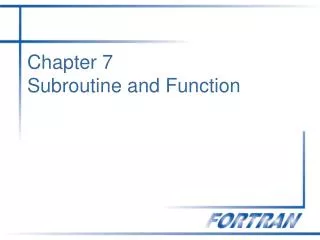
Chapter 7 Function-Architecture Codesign Paradigm. Function Architecture Co-design Methodology. System Level design methodology Top-down ( synthesis ) Bottom-up ( constraint-driven ). Synthesis. Verification. Function. Architecture. Trade-off. Mapping. Refinement. Abstraction. HW.

E N D
Function Architecture Co-design Methodology • System Level design methodology • Top-down (synthesis) • Bottom-up (constraint-driven)
Synthesis Verification Function Architecture Trade-off Mapping Refinement Abstraction HW SW Trade-off Co-design Process Methodology
Function casts a shadow Refinement Constrained Optimization and Co-design Abstraction Architecture sheds light System Level Design Vision
Main Concepts • Decomposition • Abstraction and successive refinement • Target architectural exploration and estimation
Decomposition • Top-down flow • Find an optimal match between the application function and architectural application constraints (size, power, performance). • Use separation of concerns approach to decompose a function into architectural units.
Abstraction & Successive Refinement • Function/Architecture formal trade-off is applied for mapping function onto architecture • Co-design and trade-off evaluation from the highest level down to the lower levels • Successive refinement to add details to the earlier abstraction level
Target Architectural Exploration and Estimation • Synthesized target architecture is analyzed and estimated • Architecture constraints are derived • An adequate model of target architecture is built
Main Steps in Co-design and Synthesis • Function architecture co-design and trade-off • Fully synthesize the architecture? • Co-simulation in trade-off evaluation • Functional debugging • Constraint satisfaction and missed deadlines • Processor utilization and task scheduling charts • Cost of implementation • Mapping function on the architecture • Architecture organization can be a pre-designed collection of components with various degrees of flexibilities • Matching the optimal function to the best architecture
Function/ Architecture Co-design vs. HW/SW Co-design • Design problem over-simplified • Must use Fun./Arch. Optimization & Co-design to match the optimal Function to the best Architecture 1. Fun./Arch. Co-design and Trade-off 2. Mapping Function Onto Architecture
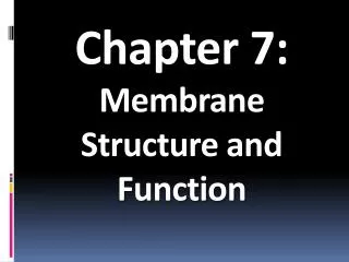
Reactive System Co-synthesis(1) CDFG Representation Control-dominated Design EFSM Representation HW/SW Map Decompose Map EFSM: Extended Finite State Machines CDFG: Control Data Flow directed acyclic Graph
EFSM BEGIN S0 a:= 5 CDFG Case (state) S2 S1 S0 S1 a:= a + 1 S2 a := 5 a := a + 1 emit(a) a state :=S1 state :=S2 END Reactive System Co-synthesis(2) Mapping • CDFG is suitable for describing EFSM reactive behavior but • Some of the control flow is hidden • Data cannot be propagated
a:= 5 EFSM Representation Optimized EFSM Representation a:= a + 1 a:= 6 a a Data Flow Optimization S0 S1 S2
Optimization and Co-design Approach • Architecture-independent phase • Task function is considered solely and control data flow analysis is performed • Removing redundant information and computations • Architecture-dependent phase • Rely on architectural information to perform additional guided optimizations tuned to the target platform
Architecture Function Graphical EFSM Esterel Reactive VHDL Constraints Specification Decomposition Estimation and Validation FFG Behavioral Optimization Functional Optimization SHIFT (CFSM Network) AFFG Macro-level Optimization AUX Modeling Cost-guided Optimization Micro-level Optimization Resource Pool SW Partition BUS HW Partition Processor Interface Interface HW1 HW5 RTOS HW/SW RTOS/Interface Co-synthesis HW2 HW4 HW3 Concrete Co-design Flow
Function/Architecture Co-Design Design Representation
Design fsm fsm data f. data f. Application O I Decomposition IDR processors Function/Architecture Optimization and Co-design ASICs data Mapping SW Partition BUS HW Partition Processor Interface Interface HW1 HW5 control RTOS Hardware/Software Co-synthesis i/o HW2 HW4 HW3 Abstract Co-design Flow
Unifying Intermediate Design Representation for Co-design Design Functional Decomposition Architecture Independent Intermediate Design Representation IDR Architecture Dependent Constraints SW HW
Platform-Based Design Source: ASV
Models and System • Models of computation • Petri-net model (graphical language for system design) • FSM (Finite-State Machine) models • Hierarchical Concurrent FSM models • POLIS system • CFSM (Co-design FSM) • EFSM (Extended FSM): support for data handling and asynchronous communication
CFSM • Includes • Finite state machine • Data computation • Locally synchronous behavior • Globally asynchronous behavior • Semantics: GALS (Globally Asynchronous and Locally Synchronous communication model)
F B=>C C=>F G C=>G C=>G F^(G==1) C C=>A CFSM2 CFSM1 CFSM2 CFSM1 C C=>B A B C=>B (A==0)=>B CFSM3 CFSM Network MOC Communication between CFSMs by means of events MOC: Model of Computation
System Specification Language • “Esterel” • as “front-end” for functional specification • Synchronous programming language for specifying reactive real-time systems • Reactive VHDL • Graphical EFSM
Intermediate Design Representation (IDR) • Most current optimization and synthesis are performed at the low abstraction level of a DAG (Direct Acyclic Graph). • Function Flow Graph (FFG) is an IDR having the notion of I/O semantics. • Textual interchange format of FFG is called C-Like Intermediate Format (CLIF). • FFG is generated from an EFSM description and can be in a Tree Form or a DAG Form.
Design Refinement Restriction Functional Decomposition Architecture Independent FFG I/O Semantics Constraints Architecture Dependent EFSM Semantics AFFG SW HW (Architecture) Function Flow Graph
FFG/CLIF • Develop Function Flow Graph (FFG) / C-Like Intermediate Format (CLIF) • Able to capture EFSM • Suitable for control and data flow analysis EFSM FFG Optimized FFG CDFG Data Flow/Control Optimizations
Function Flow Graph (FFG) • FFG is a triple G = (V, E, N0) where • V is a finite set of nodes • E = {(x,y)}, a subset of VV; (x,y) is an edge from x to y where x Pred(y), the set of predecessor nodes of y. • N0V is the start node corresponding to the EFSM initial state. • An unordered set of operations is associated with each node N. • Operations consist of TESTs performed on the EFSM inputs and internal variables, and ASSIGNs of computations on the input alphabet (inputs/internal variables) to the EFSM output alphabet (outputs and internal (state) variables)
C-Like Intermediate Format (CLIF) • Import/Export Function Flow Graph (FFG) • “Un-ordered” list of TESTand ASSIGN operations • [if (condition)] gotolabel • dest = op(src) • op = {not, minus, …} • dest = src1 op src2 • op = {+, *, /, ||, &&, |, &, …} • dest = func(arg1, arg2, …)
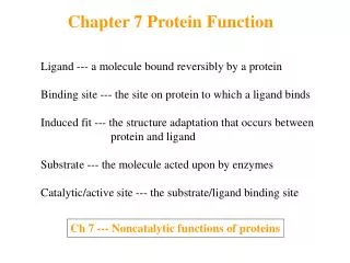
inputinp; output outp; int a = 0; int CONST_0 = 0; int T11 = 0; int T13 = 0; S1: goto S2; S2: a = inp; T13 = a + 1 CONST_0; T11 = a + a; outp = T11; goto S3; S3: outp = T13; goto S3; Preserving I/O Semantics
Legend: constant, output flow, dead operation S# = State, S#L# = Label in State S# Function Flow Graph CLIF Textual Representation y = 1 S1: x = x + y; x = x + y; a = b + c; a = x; cond1 = (y == cst1); cond2 = !cond1; if (cond2) goto S1L0 output = a; goto S1; /* Loop */ output = b; goto S1; S1 x=x+y x=x+y a= b+c a=x cond1 = (y==cst1) cond2 = !cond1; (cond2 == 1) / output(b) (cond2 == 0) / output(a) S1L0: FFG /CLIFExample
Function/Architecture Co-Design Function/Architecture Optimizations
Function Optimization • Architecture-Independent optimization objective: • Eliminateredundant information in the FFG. • Represent the information in an optimized FFG that has a minimal number of nodes and associated operations.
FFG Optimization Algorithm • FFG Optimization algorithm(G) begin while changes to FFG do Variable Definition and Uses FFG Build Reachability Analysis Normalization Available Elimination False Branch Pruning Copy Propagation Dead Operation Elimination end while end
Optimization Approach • Develop optimizer for FFG (CLIF) intermediate design representation • Goal: Optimize for speed, andsize by reducing • ASSIGNoperations • TEST operations • variables • Reach goal by solving sequence of data flow problems for analysis and information gathering using an underlying Data Flow Analysis (DFA) framework • Optimize by information redundancy elimination
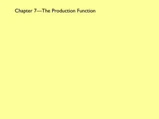
AE = f AE = f S1 t:= a + 1 S2 t1:= a + 1 t2:= b + 2 AE = {a+1} AE = {a+1, b+2} S3 a := a * 5 t3 = a + 2 AE = Available Expression Sample DFA ProblemAvailable Expressions Example • Goal is to eliminate re-computations • Formulate Available Expressions Problem • Forward Flow (meet) Problem AE = {a+1} AE = {a+2}
Data Flow Problem Instance • A particular (problem) instance of a monotone data flow analysis framework is a pair I = (G, M) where M: N F is a function that maps each node N in V of FFG G to a function in F on the node label semilattice L of the framework D.
Data Flow Analysis Framework • A monotone data flow analysis framework D = (L, , F) is used to manipulate the data flow information by interpreting the node labels on N in V of the FFG G as elements of an algebraic structure where • L is a bounded semilattice with meet , and • F is a monotone function space associated with L.
AE = {f } AE = {f } S1 t:= a + 1 S2 t1:= a + 1 t2:= b + 2 AE = {a+1} AE = {a+1, b+2} AE = {a+1} S3 a := a * 5 t3 = a + 2 AE = Available Expression AE = {a+2} Solving Data Flow Problems Data Flow Equations
Solving Data Flow Problems • Solve data flow problems using the iterative method • General: does not depend on the flow graph • Optimal for a class of data flow problems Reaches fixpoint in polynomial time (O(n2))
FFG Optimization Algorithm • Solve following problems in order to improve design: • Reaching Definitions and Uses • Normalization • Available Expression Computation • Copy Propagation, and Constant Folding • Reachability Analysis • False Branch Pruning • Code Improvement techniques • Dead Operation Elimination • Computation sharing through normalization
Function Architecture Optimizations • Fun./Arch. Representation: • Attributed Function Flow Graph (AFFG) is used to represent architectural constraints impressed upon the functional behavior of an EFSM task.
lib Architectural Information EFSM FFG OFFG AFFG CDFG Architecture Independent Sum Architecture Dependent Optimizations
F4 F3 F5 EFSM in AFFG (State Tree) Form S1 S0 F1 F0 S2 F2 F6 F7 F8
Architecture Dependent Optimization Objective • Optimize the AFFG task representation for speed of execution and size given a set of architectural constrains • Size: area of hardware, code size of software
1 y = a + b a = c x = a + b 2 3 6 y = a + b Reactivity Loop 5 4 y = a + b 7 z = a + b a = c 8 9 x = a + b 10 Motivating Example Eliminate the redundant needless runtime re-evaluation of the a+b operation
Cost-guided Relaxed Operation Motion (ROM) • For performing safe and operation from heavily executed portions of a design task to less visited segments • Relaxed-Operation-Motion (ROM): begin Data Flow and Control Optimization Reverse Sweep (dead operation addition, Normalization and available operation elimination, dead operation elimination) Forward Sweep (optional, minimize the lifetime) Final Optimization Pass end
Design Optimization Cost Estimation FFG (back-end) User Input Profiling Attributed FFG Inference Engine Relaxed Operation Motion Cost-Guided Operation Motion