Download
1 / 31
310 likes | 325 Views
Overview of the FSR-UWB technology developed at the University of Massachusetts at Amherst for BAN Networks.

E N D
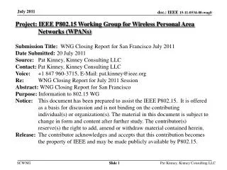
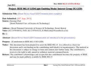
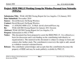
Project: IEEE P802.15 Working Group for Wireless Personal Area Networks (WPANs) Submission Title: Frequency Shifted Reference UWB Physical Layer Date Submitted: January 12, 2008 Source:Dennis L. Goeckel, PhD; Qu Zhang, PhD; Robert Jackson, PhD; Zhiguo Lai, PhD,; Department of Electrical and Computer Engineering, University of Massachusetts at Amherst, Amherst, Massachusetts Contact: Fanny Mlinarsky Voice: +1 (978) 376-5841, E-Mail: Mlinarsky@ecs.umass.edu Abstract: FSR-UWB based PHY layer for BAN Networks Purpose: Overview of the FSR-UWB technology developed at University of Massachusetts at Amherst Notice: This document has been prepared to assist the IEEE P802.15. It is offered as a basis for discussion and is not binding on the contributing individual's or organization's. The material in this document is subject to change in form and content after further study. The contributors reserve the right to add, amend or withdraw material contained herein. Release: The contributor acknowledges and accepts that this contribution becomes the property of IEEE and in March’08 it would be made publicly available by P802.15. Slide 1 Slide 1 Fanny Mlinarsky, mlinarsky@ecs.umass.edu
UMass/Amherst Wireless Center Dr. Dev Gupta Founder, Wireless Center CEO, NewLANS Dr. Dennis Goeckel Director, Wireless Center Primary Investigator on UWB research • Bringing together researchers in networking, communication systems, electromagnetics and circuits • Our goal is to get innovative ideas, projects, and prototypes in front of industry sponsors to seek direct funding and partnering opportunities for commercialization • http://www.ecs.umass.edu/wirelesscenter/ Fanny Mlinarsky, mlinarsky@ecs.umass.edu
Abstract • Overview of existing UWB signaling techniques and introduction to Frequency-Shifted Reference (FSR) Ultra-WideBand (UWB) • FSR-UWB represents a new alternative to transmitted reference (TR) UWB radio architecture [3]. • FSR-UWB is implementationally simple compared to established UWB techniques and can meet the BAN requirements. Fanny Mlinarsky, mlinarsky@ecs.umass.edu
Approaches to UWB Signaling • Coherent Impulse Radio (IR-UWB) • Multi-Band (MB-UWB) • ECMA 368 (WiMedia, aka wireless USB) • Transmitted Reference (TR-UWB) • Frequency Shifted Reference (FSR-UWB) Fanny Mlinarsky, mlinarsky@ecs.umass.edu
IR-UWB Transmitter Impulse Radio x(t) is TX signal for the lth symbol Ts symbol interval Tf frame interval 0 Tf 2Tf (Nf -1)Tf Ts b0= -1 b0=+1 0 Tf 2Tf (Nf -1)Tf Ts Ts = Nf Tf where Nf is # frames/symbol, Nf >>1 Fanny Mlinarsky, mlinarsky@ecs.umass.edu
r(t) rl LPF ……… ……… IR-UWB Rake Receiver Impulse Radio Fanny Mlinarsky, mlinarsky@ecs.umass.edu • Huge number of paths in a UWB fading channel makes the IR-UWB full rake receiver type architectures troublesome • Large number of taps required for significant energy capture • Channel estimation can be difficult [2] • These implementational issues have caused the industry to abandon impulsive UWB or direct-sequence UWB [13]
MB-UWB OFDM (ECMA-368) Multi-Band OFDM 128 subcarriers QPSK / DCM signaling 528 MHz 3.168 4.752 6.336 7.920 9.504 10.56 GHz Time-frequency Interleaving (TFI) or Fixed Frequency Interleaving (FFI) is used to spread the transmit power among the three sub-bands thereby increasing the peak transmit power and optimizing the range. Existing products operate in Band Group 1 Fanny Mlinarsky, mlinarsky@ecs.umass.edu
TR-UWB Transmitted Reference • TR-UWB was a strong candidate signaling scheme in the original effort of 802.15.4a (location and low data rate applications), but a major implementational issue – delay line – killed this approach • Eventually the group adapted burst mode PPM (pulse position modulation) • In the TR-UWB systems [3] each frame consists of two pulses • The first is a reference pulse and has a fixed polarity • The second is the data pulse and follows the reference pulse with some known delay, D • The reference pulse provides a template to which to match the data pulse Fanny Mlinarsky, mlinarsky@ecs.umass.edu
TR-UWB Transmitter Transmitted Reference Reference pulse b0=-1 (Nf -1)Tf 0 Tf 2Tf Ts Data pulse b0=+1 (Nf -1)Tf 0 Tf 2Tf Ts D Fanny Mlinarsky, mlinarsky@ecs.umass.edu
TR-UWB Receiver Transmitted Reference Multiple pulses are due to multipath in the channel An example(b = -1): r(t) 0 Tf 2Tf (Nf -1)Tf Ts …… r(t-D) Ts 0 Tf 2Tf (Nf -1)Tf D Fanny Mlinarsky, mlinarsky@ecs.umass.edu
LPF rl D TR-UWB Receiver Transmitted Reference Fanny Mlinarsky, mlinarsky@ecs.umass.edu
LPF rl D TR-UWB vs. FSR-UWB Frequency Shifted Reference TR-UWB Delay line looks simple, but how do you build it? [4]-[6] outline challenges LPF rl FSR-UWB Delay line replaced by oscillator/mixer [7]-[8] Fanny Mlinarsky, mlinarsky@ecs.umass.edu
Complexity of TR-UWB vs. Simplicity of FRS-UWB Frequency Shifted Reference • The General Electric team developed a testbed for the standard TR-UWB that required a 20-foot coaxial cable in the receiver because of the need for a 20ns wideband analog delay element [11]. • The proposed FSR-UWB system is simple enough to have been implemented by University of Massachusetts at Amherst undergraduates. • The prototype operates with at up to10 kbps in the 600 MHz-7 GHz range • Our simulations based on the latest BAN channel models demonstrate feasibility of 5 Mbps operation Fanny Mlinarsky, mlinarsky@ecs.umass.edu
FSR-UWB Principle Frequency Shifted Reference • FSR-UWB system uses a reference that is a slightly frequency-shifted version of the data-bearing signal. • The reference signal and data signal are orthogonal over a symbol interval. • For low data rates, the frequency shift between the reference signal and data signal is small compared to the channel coherence bandwidth. • The reference goes through approximately the same channel as the data signal. Fanny Mlinarsky, mlinarsky@ecs.umass.edu
Nf – Frames per Symbol for FSR-UWB vs. TR-UWB • A symbol interval Ts = Nf * Tf ; Nf frames, each of duration Tf • Nf can be increased until either: • The gains from the increased average energy are offset by the degradation due to interframe interference (IFI), or… • The FCC spectral limit is reached • FSR-UWB requires only 1 pulse per frame, vs. TR-UWB that requires 2 pulses per frame, which means that Nf can be higher for FSR-UWB, improving signal integrity • FSR-UWB is also more tolerant of IFI and, thus, can employ a higher Nf to improve average energy aggregation; • With the FCC constraint Nf,FSR=5.83*Nf,TR • Over a wide range of error probabilities and constraints, FSR-UWB offers a 1.0 to 1.5 dB gain over TR-UWB Fanny Mlinarsky, mlinarsky@ecs.umass.edu
FSR-UWB makes Practical Implementations Possible Small (TX fits on a 1.5 x 3.25” PCB), Low cost, Efficient (120 mW quiescent power) Tag transceiver including a Vivaldi antenna [10], UWB chipset and battery • FSR-UWB Based RFID Tag • UMass project: Developing silicon at the IBM 180 um foundry in Burlington, MA • SBIR Phase II, funded by US Army RTP, NC – ready for commercialization Fanny Mlinarsky, mlinarsky@ecs.umass.edu
FSR-UW Low Power Consumption 1 Mbps operation Fanny Mlinarsky, mlinarsky@ecs.umass.edu
Power Consumption Assumptions • Operational life of FSR-UWB system: 5 years (43,800 hours) • Minimum operating voltage: 1.5V Fanny Mlinarsky, mlinarsky@ecs.umass.edu
FSR-UWB Benefits • Robust in the presence of interference, multipath and electromagnetic obstructions, including metal and water content • Extremely low power - 120 mW continuous power, yielding 5 years of battery powered operation • Low cost Fanny Mlinarsky, mlinarsky@ecs.umass.edu
FSR-UWB System Considerations • In the FSR-UWB, a frequency offset between the reference impulse train and data impulse train is the inverse of the symbol period. • Pulse shaping waveform is half the frequency of the data rate and this frequency, f0 = 1/(2*TS), must be below the frequency coherence of the channel • Frequency coherence of the channel – the bandwidth over which the channel is roughly constant – is described by the channel models • Symbol timing, δ, must also be synchronized [symbol clock] • This can be achieved using adaptive algorithms to minimize Е[Λ2(δ)] versus δ Fanny Mlinarsky, mlinarsky@ecs.umass.edu
Proposed synchronization metric Е[Λ2(δ)] versus δ in normalized symbol periods for a system with parameters given in [8]. The system can be synchronized by finding the δthat results in the maximum receiver output energy. Fanny Mlinarsky, mlinarsky@ecs.umass.edu
Receiver for the proposed FSR-UWB system The delay element of the standard TR-UWB scheme has been replaced by a mixer in (a). Since multiplication is commutative, the receiver in (a) can be drawn in the more convenient form given in (b). Fanny Mlinarsky, mlinarsky@ecs.umass.edu
FSR-UWB receiver diagram showing the unknown time synchronization parameter, δ [8] Clock recovery and phase synching of the shaping oscillator are both tied to δ, which is fed back from the signal processing block in the RX Fanny Mlinarsky, mlinarsky@ecs.umass.edu
BER probability vs. peak pulse energy to noise ratio Еb/No on a BAN channel per IEEE P802.15-08-0780-04-0006 document Data rate: 5 Mbps Pulse: 2nd derivative Gaussian pulse of width 0.5 ns (roughly 10 GHz of bandwidth) Frames per bit: 20 Frame length: 10 ns The bold red line is the average of 1000 runs and the bold green line is the average of 980 runs excluding the worst 20. Fanny Mlinarsky, mlinarsky@ecs.umass.edu
BER probability vs. peak pulse energy to noise ratio Еp/No on an AWGN channel for FSR-UWB Tf = 40 ns and Rb = 1/(Nf * Tf ) Zero-to-zero pulse width = 0.25 ns Solid lines represent simulation results; dashed-lines represent analytical results from [8] equation (10). Fanny Mlinarsky, mlinarsky@ecs.umass.edu
BER probability vs. Еp/No for FSR-UWBExtreme Doppler Shift Fast fading multipath channel – the multipath fading channel changes independently from frame to frame. System I 25 frames of length 50 ns System II 25 frames of length 20 ns Fanny Mlinarsky, mlinarsky@ecs.umass.edu
FSR-UWB Demo • 2006 UWB Workshop in California sponsored by the army research office • Published papers can be found at http://www-unix.ecs.umass.edu/~goeckel/uwb.html FSR-UWB prototype Fanny Mlinarsky, mlinarsky@ecs.umass.edu
References (1 of 3) [1] IEEE 802.15 WPAN Low Rate Alternative PHY Task Group 4a (TG4a), “http://www.ieee802.org/15/pub/TG4a.html.” [2] M. Z. Win and R. A. Scholtz, “On the energy capture of ultra-wide bandwidth signals in dense multipath environments,”IEEE Commun. Lett., vol. 2, pp. 245–247, Sept. 1998. [3] R. Hoctor and H. Tomlinson, An overview of delay-hopped, transmittedreference RF communications, General Electric Technical Report 2001CRD198, Jan. 2002. [4] M. Casu and G. Durisi, “Implementation aspects of a transmittedreference UWB receiver,” Wireless Communications and Mobile Computing, Vol. 5: pp. 537-549, May 2005. [5] L. Feng and W. Namgoong, “An oversampled channelized UWB receiver with transmitted reference modulation,” to appear in the IEEE Transactions on Wireless Communications. [6] S. Bagga, S. Haddad, W. Serdijn, J. Long and E. Busking, “A delay filter for an IR-UWB front-end,” Proceedings of the IEEE International Conference on Ultra-wideband, pp. 323-327, Sept., 2005. Fanny Mlinarsky, mlinarsky@ecs.umass.edu
References (2 of 3) [7] D. Goeckel and Q. Zhang, “Slightly frequency-shifted reference ultrawideband (UWB) radio: TR-UWB without the delay element,” Proceedings of the Military Communication Conference, Oct., 2005. [8] D. Goeckel and Q. Zhang, “Slightly frequency-shifted reference ultrawideband (UWB) radio”, revision submitted to the IEEE Transactions on Communications. [9] Q. Zhang and D. Goeckel, “Multi-Differential Slightly Frequency-Shifted Reference Ultra-Wideband (UWB) Radio,” Proceedings of the Conference on Information Sciences and Systems, March 2006. Fanny Mlinarsky, mlinarsky@ecs.umass.edu
References (3 of 3) [10] A. Stigliari, “Design and characterization of a planar ultra-wide band antenna”, MS dissertation, Electrical and Computer Engineering, University of Massachusetts Amherst, Feb., 2005. [11] N. van Stralen, A. Dentinger, K. Welles II, R. Gaus Jr., R. Hoctor, and H. Tomlinson, ”Delay hopped transmitted reference experiemental results”, Proceedings of UWBST, pp. 93-98, May 2002. [12] J. Proakis and D. Manolokis, Digital signal processing, Prentice-Hall, third edition, 1996. [13] A. Batra, J. Balakrishnan, G. Aiello, J. Foerster, and A. Dabak, “Design of a Multiband OFDM System for Realistic UWB Channel Environments,” IEEE Transactions on Microwave Theory and Techniques, Vol. 52: pp. 2123-2138, September 2004. Fanny Mlinarsky, mlinarsky@ecs.umass.edu
Contact Information • Dr. Dennis Goeckel, Ph.D.Director, Wireless Communications CenterProfessor, Electrical and Computer Engineering(413) 545-3514goeckel@ecs.umass.edu • Fanny MlinarskyExecutive Director, Wireless Communications Center(978) 376-5841mlinarsky@ecs.umass.edu Fanny Mlinarsky, mlinarsky@ecs.umass.edu