Download
1 / 23
230 likes | 248 Views
Review of the electronics system for the CMS drift tube chambers read-out system at CERN on November 3rd, 2003. Includes design requirements, ROB architecture, HPTDC features, and more.

E N D
The Read-Out system for the CMS Drift Tube Chambers. Electronics System Review CERN. November 3rd, 2003
2 ESR FOR MUON DT MINICRATE SYSTEM. The Read-Out System. November 3rd , 2003 Index The Read-Out System. Design Requirements. Read Out Board 1. 2. 3. HPTDC (High Performance Time to Digital Converter). ROB architecture and other features ROB validation tests ROB production Conclusions 4. 5. 6.
3 ESR FOR MUON DT MINICRATE SYSTEM. The Read-Out System. November 3rd , 2003 Read-Out System The Read-Out system of the CMS DT chambers is based on the READ OUT BOARDS (ROB). Its aim is: the time digitalization of the incoming signals from the Front-End electronics of the DT chambers. the data transmission to the ROS boards, located in the towers in the periphery of the detector, from there to further levels of the DAQ.
4 1 Superlayer Φ 1 Superlayer θ Honeycomb 1 Superlayer Φ MINICRATE ROB ESR FOR MUON DT MINICRATE SYSTEM. The Read-Out System. November 3rd , 2003 Location in the CMS Detector
5 ESR FOR MUON DT MINICRATE SYSTEM. The Read-Out System. November 3rd , 2003 Design Requirements RATES 40.08 MHz clock 1034 cm-2s-1 luminosity, at 25 ns bunch crossing => 10 Hz/cm-2 charged particles rate. L1 Accept reduces to 1 Hz/cm2 of muons => 250 DT-chambers, a total of 172,200 anode channels. Overlapping triggers due to a drift time of ~400 ns. Trigger latency of 3.2 s. 100 kHz triggers ~ 1 kHz muon hits/DT chamber cell. neutron fluence 10 years < 1010cm-2 charged particles flux < 10 cm-2s-1 10 year integrated dose ~ 1 Gy ENVIRONMENTAL RADIATION Radiation hard devices are not going to be employed, radiation tests have to be performed to every component. OTHERS Stray magnetic fields, in the barrel region around 0.08 Tesla. Limited maintenance for 10 years of operation.
6 Tmax drift time~400 ns >> Tbunch crossing 25 ns 2 3 1 4 1 2 3 4 Overlapping Bunch crossing Drift Time Trigger L1 Accept Latency ESR FOR MUON DT MINICRATE SYSTEM. The Read-Out System. November 3rd , 2003 Time Digitization Vdrift ~ constant t ~ x Time measurement with respect to L1 Accept
7 ESR FOR MUON DT MINICRATE SYSTEM. The Read-Out System. November 3rd , 2003 HPTDC (High Performance Time to Digital Converter) Developed by the CERN/EP-MIC group, and produced by IBM in 0.25 m CMOS technology. 4 registers/channel before L1 buffer. 4 L1 buffers of 256 words, each shared by 8 channels. Triggers stored in 16 words deep FIFO. 256 words deep readout FIFO.
8 HPTDC LHC clock operation (40.08MHz). Highly programmable which provides flexibility. High integration, 32 channels per chip. Overlapping trigger handling. Trigger latencies (50 μs) large enough to accommodate our requirements (3.2μs). Time resolution of ~265 ps RMS in low resolution mode (Required resolution~1ns) Implemented in a radiation tolerant technology, up to levels of 30 Krad total dose with slight increase in power consumption. Up to 2MHz hit rates, much more than our needs (noisy channels ~ tens of KHz). Minimum time between pulses ~10 ns. Up to 1 MHz trigger rates, enough for 100 KHz maximum estimated. Bunch and event identification. JTAG port for programming and monitoring. Flexible read-out interface: parallel, serial or byte-wise. Error flags signalling lost of events, TDC internal errors, etc. and self-bypass on error. ESR FOR MUON DT MINICRATE SYSTEM. The Read-Out System. November 3rd , 2003 OTHER FEATURES
9 READ-OUT INTERFACE DIAGRAM parity) Serializer clock ESR FOR MUON DT MINICRATE SYSTEM. The Read-Out System. November 3rd , 2003 ROB Architecture JTAG INTERFACE DIAGRAM 4 HPTDC/ROB (128 channels) Compromise between #boards and #unused channels. A JTAG interface for configuration and monitoring. Clock synchronous token ring passing scheme where one TDC is configured as Master. Bypass on error mechanism implemented.
10 Power consumption: 2.5 V (0.5A) and 3.3V (0.5A) ~ 4 W => ~ 6kW whole system. Power supply protection circuitry: In case of 2.5V current consumption over 1.5 A or 3.3V over 1A, power supply is disconnected, with powering on cycles every 700 ms (reduces to 10% power consumption). Sensor on board for temperature, 2.5V and 3.3V voltage and 2.5 V current monitoring. (Maxim DS2438). ESR FOR MUON DT MINICRATE SYSTEM. The Read-Out System. November 3rd , 2003 Other ROB Features READ-OUT 32 bits/HPTDC word Master header and trailer Error signaling Timing and positional information (# TDC and # channel). Byte-wise readout (8 bits data+1 parity+2 byte ID) DS92LV1021 serializer (12 bits: 10 data + 2 start/stop) at 20 MHz. POWER SUPPLY
11 FF1 0 d 0 FF2 1 q 2 FF3 3 1 ESR FOR MUON DT MINICRATE SYSTEM. The Read-Out System. November 3rd , 2003 Other ROB Features ALTERA CPLD CONTROLLER - An Altera CPLD (EPM7128AE) manages the the Data_Ready/Get_Data transmission protocol slowing down the readout frequency to 20 MHz. - Manages the channels enabling mechanism for testing chambers during spill interleaves, simulating artificial tracks. -Controls bytes order from HPTDC words. Triple redundancy on ALTERA FPGA registers. Allows detection and reparation of 1 bit upset in a CPLD register due to Single Event Upsets (SEU) from radiation. (Updated every 25 ns). SEU <= (FF1 xor FF2) or (FF1 xor FF3) or (FF2 xor FF3) Also a SEU counter implemented for radiation tests.
12 TEST MODE Enable TDC 0 ch 0-3 Enable TDC 0 ch 0-7 T1 Enable TDC 0 ch 7-12 ... T2 T3 ESR FOR MUON DT MINICRATE SYSTEM. The Read-Out System. November 3rd , 2003 Test Pulses mode Mode operation for testing chamber channels and electronics during spill interleaves, simulating artificial tracks. Originated by a TTC command. CCB enables/disables the different channels of the Front-End boards and ROB´s to simulate individual vertical tracks. Front-End generates the Odd and Even signals of the corresponding layer, delayed one with respect to the other to simulate a vertical track on any position of the cell. (Trigger system test). Altera CPLD manages the mechanism of enabling/disabling accordingly the ROB LVDS receiver channels.
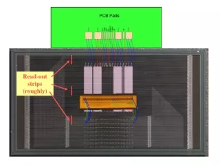
13 128 LVDS signals from DT chambers. Transmitted to Trigger logic, previously converted to TTL level. ROBUS (RO-MC control bus): Independent point to point clock connections are used to minimise interference effects. FTP Cat.6 cable for ROB-ROS link. - Independent powering up signals (up to 7 ROB´s) - ROB address lines (4, up to 15 boards) - JTAG lines - other control lines (test pulses...) ESR FOR MUON DT MINICRATE SYSTEM. The Read-Out System. November 3rd , 2003 ROB Connections TRB connections From DT chambers 3.3V power supply 22.6 cm Thermal dissipation areas 9.8 cm ROBUS (back) ROB-ROS link 40MHz clock
14 Read Out Boards (ROB) Link bandwidth: 240 Mbps. Throughput: 16Mbps. Measured BER < 10-15 30m FTP Cat. 6 AC coupled LVDS link DT chamber 1500 Towers DDU 60 USC55 Control Room 100 m. Optical link Link max. Bandwidth: 800Mbps. Throughtput: 270Mbps. Read Out Server boards (ROS) ESR FOR MUON DT MINICRATE SYSTEM. The Read-Out System. November 3rd , 2003 ROB-ROS link CMS DETECTOR
15 MB4 MB3 MB2 TRB TRB TRB SB MB1 ESR FOR MUON DT MINICRATE SYSTEM. The Read-Out System. November 3rd , 2003 Minicrate (MC) 250 Minicrates 1500 ROB´s: -1440 Rob-128 -60 ROB-32 Power supply 3.3V @ 40A 5V @ 1.5A to ROS MINICRATE Chamber signals Link board RO- Link board ROBUS ROB ROB ROB CCB 40 MHz CLOCK RO-link TTC+Slow control
16 Nº events Time box Time (ns) Oct. 01: test beam at GIF. Including a 25 ns structured beam ~ 5 Ktrig/s. MB2 chamber operated under real gas and voltage conditions. With and without gamma background during acquisition. May. 03: One full Minicrate operational with a Ros-8 prototype. Validation with overlapping triggers No significant errors were found neither in HPTDC nor in the ROB design, (incorrect wordcount when using local headers). TDC can stand high hit rates, including noisy channels (~MHz) and this only affects 1 group of 8 channels. ESR FOR MUON DT MINICRATE SYSTEM. The Read-Out System. November 3rd , 2003 ROB Validation Tests TEST BEAMS AT GAMMA IRRADIATION FACILITY, GIF. (CERN)
17 ESR FOR MUON DT MINICRATE SYSTEM. The Read-Out System. November 3rd , 2003 ROB Validation Tests IRRADIATION TESTS Cyclotron Research Centre at the Catholic University of Louvain (UCL), Belgium. 60 MeV proton irradiation. Fluence: 5·1010 p.cm-2 SEU: MTBFHPTDC = 3.8 days in the whole detector MTBFALTERA = 3.4 days in the whole detector Regulators (MIC29151-3.3BU, MIC39151-2.5BU): ΔV<1% Rest of ROB IC´s: No effect
18 ESR FOR MUON DT MINICRATE SYSTEM. The Read-Out System. November 3rd , 2003 ROB Validation Tests TEMPERATURE CYCLING 70ºC 0.2ºC/min 0ºC - Regulators: Small variations (< 5mV/30ºC). - 2.5V current variations of 0.4 mA/ºC. - Timing measurement variation: 900 ps/70ºC (14 ps/ºC).Max variation ~ 45 ps/ºC. 30% due to LVDS receivers (DS90LV048). LIFETIME TESTS - ROB fully operational at 105ºC ambient temperature for 4 months (3100 hours). - No device has shown any failure.
19 Time shift < 200 ps Neighbour channels crosstalk Time measurement shift in one ROB channel due to neighbour signals. ESR FOR MUON DT MINICRATE SYSTEM. The Read-Out System. November 3rd , 2003 ROB Validation Tests Time resolution Low resolution bin size: 0.781 ns Measured resolution: 265 ps Link reliability RO link to ROS-8 prototype has been tested using a TTC system (TTCvi, TTCex, TTCrx). Measured jitter on ROB with TTC clock: ~40ps RMS; ~380ps pk-pk BER < 10-15 No observed influence of TTC commands.
20 ESR FOR MUON DT MINICRATE SYSTEM. The Read-Out System. November 3rd , 2003 ROB Production Several prototypes of ROB´s have been made, we are now confident on its operation. PCB´s for ROB-128 and ROB-32 have already been produced. An error was found in the engineering run of the HPTDC that never showed up before, presumably due to metallization process. Its consequence is a very low yield of the produced HPTDC´s. Exhaustive tests that identify the error have been developed. Production run showed 350 “good” HPTDC´s received in September, they will be used for: -180 ROB´s of the first assembly batch. - Produce all ROB-32: 60+spares. Whole final production batch of HPTDC´s, now being packaged, will be available in December (6000 u.) - Remaining ROB-128 will be produced then.
21 ESR FOR MUON DT MINICRATE SYSTEM. The Read-Out System. November 3rd , 2003 ROB Production Assembly is done at the industry: Assembly On error: repairing Connectorization tests. On error: repairing Functional test. A test that checks every functionality of the ROB has been developed at Ciemat to validate assembled ROB´s at the industry.
22 ESR FOR MUON DT MINICRATE SYSTEM. The Read-Out System. November 3rd , 2003 ROB Production Before assembling ROB´s in the Minicrates, they will go through a BURN-IN process: -We do not want to over-stress the boards, only find infant mortality. - 15 days at 60ºC ambient temperature powered and clocked.
23 ESR FOR MUON DT MINICRATE SYSTEM. The Read-Out System. November 3rd , 2003 Conclusions The design and operation of the ROB has been thoroughly tested with satisfactorily results. It meets the imposed requirements of reliability and accuracy. We are confident in the proper operation of these boards inside the CMS environment within the expected radiation levels, trigger and data rates, etc. Accordingly, the Read-Out Board is ready for final production and installation on Minicrates.