Download
1 / 22
220 likes | 242 Views
The GLAST-LAT Calibration Unit Beam Test at CERN Luca Latronico luca.latronico@pi.infn.it. LAT-CU Beam Test Workshop INFN-Pisa – 20-21 March 2006. Introduction to the workshop. Beam Test overview slides (to udpate all participants about what we are doing and plan to do)

E N D
The GLAST-LAT Calibration Unit Beam Test at CERN Luca Latronico luca.latronico@pi.infn.it LAT-CU Beam Test Workshop INFN-Pisa – 20-21 March 2006
Introduction to the workshop • Beam Test overview slides (to udpate all participants about what we are doing and plan to do) • Motivations and goals for the CERN beam test • Experimental setup • Status of activities • Why this workshop • Gather the key people • Define an exhaustive list of tasks • Define milestones • Share work and responsibilities • Mandatory: find/agree on solutions for discussions on the table – beam starts in 4 months from now!
Introduction to the workshop • How this workshop • Overview presentations on current activities and past experiences • Plenary discussion on key topics (20-21 march) • DAQ systems and data streams • how to merge data from CU and ancillary systems • Beam Test Plan • Define run configurations (particle, energy, angles, positions, statistics) as a function of analysis goals • Offline infrastructure • Local and SLAC pipeline, network issues, sim/recon tools • Operations at CERN • All practical issues (site access, safety, network, shifts … ) • Data Analysis • Follow up of plenary discussions and start of activities in dedicated working groups (this is a working week!), plus • Technical discussions for MGSE interfaces, flight hardware integration, handling, test • Simulation and reconstruction working group • organize a data analysis working group
Motivations • Most events on orbit contained in 2 towers, no available beam to irradiate full LAT – therefore calibration on a smaller unit is good enough • Sampling phase space on the full flight LAT very demanding in cost and schedule • MonteCarlo techniques and tools have become extremely sophisticated and reliable • The LAT calibration, background rejection strategy and performance parameterization heavily rely on our LAT MonteCarlo • we need to tune our MonteCarlo description against real data • we need to validate the Geant4+Gleam simulation of the relevant physical processes for the LAT
Goals – hot areas • Point Spread Function • Requires tagged photons, low energy is critical • Effective area • Energy reconstruction • electromagnetic interactions modeling • Reconstruction algorithms test • Backsplash • Rates, spectra, topology • Hadronic interactions modeling and background rejection • Compare and identify best hadronic physics list • Test background rejection • Geant4 validation • Flight electronics response • Test with different particles and energies • High rate behaviour • Method: measure low level responses (cluster sizes, topologies), build higher level distributions (PSF, Aeff) and compare with MC, then tune
Our test in the CERN site • Why CERN? • e- and hadron beams available • high energy available • continuous beam • past experience (AGILE at T9, GLAST-CAL at SPS) • optimization resources with LAT I&T and ramping up to ISOC only if european GLAST members take leading role in the calibration beam test • H4 line located in the North experimental area of the CERN Prevessin site (France) • Beam extracted from SPS • T9 line located in the East experimental area of the CERN Meyrin site (Switzerland) • Beam extracted from PS
Official CERN PS schedule • 4 weeks at T9/PS, July 27 – august 22 • ~1 day w/o beam per week for accelerator maintainance (MD) • Setup and tuning expected more demanding • It’s the first • Will need to CU sanity check after transportation (might use CR out of the area but we don’t have an allocated space yet, maybe not easy to get for a 1ton equipment) • Many ancillary systems to setup and integrate for different beams identification and data taking BUT previous experience from INFN-Bari in Si-TRD experiment
Official CERN SPS schedule • 2 weeks + 1 day at H4/SPS, 4-18 September • 11 day before just reserved and not assigned, hope for more • ~1 day w/o beam per week for accelerator maintainance (MD) • 2 weeks separation to move setup between N and E areas • Will need a controlled storage area • Setup in H4 must be smooth because of limited time • Reduced number of ancillary systems • TRD calibration performed at PS
Beam dump (current simulation 40X0 W) PS-T9 setup Brem g 50MeV few~GeV e-, p , p 1-15GeV NaI CAL S3 Si4 Si3 CU magnet T2 S4 T1 S1 Si1 Si2 S2 C1 C2 TRD • C1-C2: Cerenkov counters from CERN (e/p PID ) • S1-S2-S3-S4 (maybe not all): trigger/veto scintillators • TRD (for calibration at PS, required at SPS, e/p PID): 16 modules with radiator and double straw tubes • Si-n: silicon detectors with 384 strips for g-tagger • NaI CAL: g-tagger calibration, enough as dump (~<20X0)? • Hall length is 8 mt max: • T1-T2: Time Of Flight scintillators (protons PID) – hard calibration, currently NA, need to plan for it! • Beam dump required to avoid hitting CU with deviated e- beam Page Number
SPS-H4 setup e-, p , p 10-300GeV CU S1 S2 C1 C2 TRD • C1-C2: Cerenkov counters (e/p PID ) • S1-S2: trigger scintillators • TRD (e/p PID) Magnet (will be off) XY table if used as a support address interface issues if CU downstream beam height similar to PS BUT must free area from equipment Page Number
Particles ~400ms Magnet cycle Intensity Spilled beam structure advice using off-spill time to write to disk and merge data SPS master cycle ~14s (details depends on SPS setup – we may have 2 spills/cycle) can we do this within spills? To what extent? Offline beam test N-tuple SVAC basic n-tuple + ancillary data (at least part ID and E) Ancillary recon (g-TAG recon work within spills) part ID: g/e-/p/p g energy (dE/dX?) Ancillary raw data stream 1536 Strips PH (4 Si planes) Max 32 straw tubes PH Few PMs Event Time-stamp PS/SPS spill signal time-stamp g-TAG TRD Cerenkov • External trigger • current baseline is to use artificial trigger veto after each trigger that is long enough for slowest system to readout the event • LDF level merge and DAQ merge w/o such veto will be explored at the workshop Data streams merge event time-stamps within given window for every spill (as defined by PS/SPS spill signal) LAT recon • Ancillary systems Online externaltrigger efficiency trend • tagger/TRD diagnostics Tracks in tagger Si beam profiles Si hit multiplicity Si PH distribution …. LDF file CU Online TKR, CAL standard plots Meaningful plots for specific study (backsplash, PSF ….) CU Page Number
Integration and Test Current status • Integration & test activities • 1x1 tower completed and under test to exercise calibrations and develop DAQ/monitor • Parts procurement well in progress • I&T strategy defined and to be agreed in this workshop • DAQ • Standalone CU-DAQ with LATTE 4 • External CR trigger running – will be used to synchronize with ancillary DAQ during workshop • Dedicated monitor under development (see Baldini’s talk) • Ancillary systems • Complete system from INFN-BA capable of reading all ancillaries available for synch test during workshop (no detectors) • Full g-tagger system (detectors plus DAQ) available next week • Will define final DAQs, required developments and synchronization strategy CR trigger TKR HKP PC CAL (inside) Bay (outside) TEM/TPS CR trigger logic CR trigger Ext trigger box CU VME PS GASU Rotation stand – will extend to 1x4
Integration and Test Schedule we can make it and could be at CERN taking CR ~ mid july • Good scores • all material from SLAC shipped • full material procurement for integration will be completed next week • Ancillary systems integration test this week • Critical items • Grid rework (company constraints) • Proof tests outcome • CAL and TKR delivery • MGSE Alignment tools delivery
CU Integration at INFN • Rotation stand from SLAC • Modified CAL integration strategy (from bottom) to cope with limited ceiling in our clean room • See talk by Nicola Saggini and Francesco Bellardi
MGSE - Inner Shipping Container (ISC) • Designed to minimize beam interference (thin walls) • Temperature and humidity control • Interface to CU, integration tools, XY table and ACD tiles (definition of all interfaces is a goal for this workshop) • See talk by Andrea Tenze FREE board 1mm Al window (non-structural) GASU Thick structural Al window VME Crate + 28Vexternal PS
MGSE - XY scanning table See talk by Oscar Ferreira for details Interface with ISC will be agreed in this workshop
MGSE - Outer Shipping Container (OSC) • This is heavy stuff! • ~1.5ton weight • Designed for • Transportation • Storage • Contamination control outside clean areas • Humidity control (sealed) • Full proof tests campaign foreseen • See talk by Michele Pinchera on wednesday
Beam test plan discussion • Current draft is a good starting point, with most of what we want inside, BUT we need to • make sure all analysis-driven requirements in terms of running configurations and statistics are met • we don’t miss a chance for a meaningful and important measurement • Current draft should be covered in allocated time BUT what about contingency? We need to • Optimize program • Minimize overlap between PS and SPS • as a rule of thumb it makes sense to concentrate more measurements at PS due to more allocated time • Evaluate beam composition and tagging efficiencies to estimate real data taking time for a defined goal and choose right beam and setup • Define list of priorities (especially at SPS where time is limited, and beam instabilities can flaw our plan)
Draft Beam Test Plan at PS * *** ** * Beam position limits for off-axis angles Some things to discuss * 6 positions might be too many for some angles >0 ** 4 ranges cross-calibration for 4 CAL modules (+ CsI log light attenuation for 1 CAL) • should we limit cross-calibration on 1 or 2 CAL only? • p contamination at T9 for 15GeV e- is >90% *** should we consider radiation effect on TEMs? ** proposed pattern
Draft beam test plan at SPS * ** *** Some things to discuss * 10 GeV overlap PS energy range – keep it for cross-check? ** consider special runs to study optimization of TKR GTRC buffer size to avoid saturating GTCC limitation in showers? • scan several GTRC size values for on-axis high energy beam *** energy sampling enough for (and same apply to PS) • EM/Had identification? • Choose correct G4 hadronic physics list?
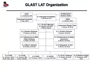
Expected outcome from the workshop Organize work ahead and fill in organization chart • DAQ baseline and data streams • Offline infrastructure • Beam test plan • identify required analysis to complete it • Operations • identify contact people and responsible for all issues • Mechanics, I&T, flight hardware handling plan • agree an draft procedures • plan final review • Data analysis • shape up a group • identify milestones and support beam test plan finalization
GLAST land at CERN – summer 2006 • Lots of exciting work ahead in many areas • we must commit to make it a success • join the working groups and have a nice workshop