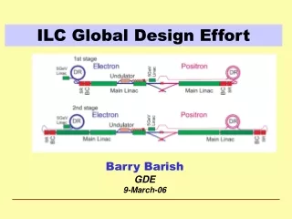
Designing the ILC Superconducting RF Main Linac: Key Decisions and Global Coordination
320 likes | 444 Views
This document covers the development of the International Linear Collider (ILC) Superconducting RF Main Linac at SLAC. It details the Global Design Effort (GDE), which began at Snowmass, and includes the outlining of the baseline configuration for the ILC. Present GDE membership is articulated across the Americas, Europe, and Asia. Key technical decisions regarding luminosity parameters and gradient choices are discussed. The document serves as a reference for the technical design timeline, configuration management, and R&D program evolution towards achieving the project's goals.

Designing the ILC Superconducting RF Main Linac: Key Decisions and Global Coordination
E N D
Presentation Transcript
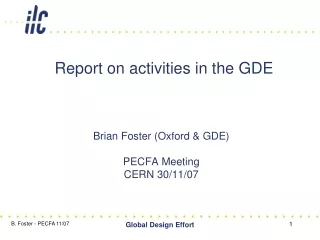
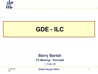
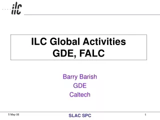
ILC Global ActivitiesGDE, FALC Barry Barish GDE Caltech SLAC SPC
Designing the ILC Superconducting RF Main Linac SLAC SPC
GDE Began at Snowmass Snowmass 49 GDE members --------- Present GDE Membership Americas 22 Europe 24 Asia 18 About 30 FTEs SLAC SPC
2005 2006 2007 2008 2009 2010 Global Design Effort Project Baseline configuration Reference Design ILC Timeline …. Technical Design ILC R&D Program Expression of Interest to Host International Mgmt SLAC SPC
Schematic of the BCD SLAC SPC
Baseline Configuration Document • Our ‘Deliverable’ by the end of 2005 • A structured electronic document • Documentation (reports, drawings etc) • Technical specs. • Parameter tables • Revisions and Evolution through Change Control Process http://www.linearcollider.org/wiki/doku.php?id=bcd:bcd_home SLAC SPC
The Key Decisions Critical choices: luminosity parameters & gradient SLAC SPC
Making Choices – The Tradeoffs Many decisions are interrelated and require input from several WG/GG groups SLAC SPC
Parametric Approach SLAC SPC
Baseline Configuration Document • Latest Official Version of BCD • BCD in MSWord files: • All-in-one-file • Single PDF File (2582kB, Updated Mar.28, 2006) • Single MSWord File (5103kB, Updated Mar.28, 2006) • By Area Nodes: • General Parameters (233kB, Updated Mar. 3, 2006) • Electron Source (296kB) • Positron Source (316kB) • Damping Rings (554kB, Updated Feb.27, 2006) • Ring to Main Linac (313kB, Updated Mar.28, 2006) • Main Linacs (455kB) • Beam Delivery (543kB) • TeV Upgrade Scenario (26kB) SLAC SPC
Primary e- source Beam Delivery System IP 250 GeV e- DR Positron Linac 150 GeV 100 GeV Helical Undulator In By-Pass Line Photon Collimators e+ DR Target e- Dump Photon Beam Dump Photon Target Adiabatic Matching Device e+ pre-accelerator ~5GeV Auxiliary e- Source Positron Source • Helical Undulator Based Positron Source • with Keep Alive System Keep Alive: This source would have all bunches filled to 10% of nominal intensity. SLAC SPC
Beam Delivery System • Baseline (supported, at the moment, by GDE exec) • two BDSs, 20/2mrad, 2 detectors, 2 longitudinally separated IR halls • Alternative 1 • two BDSs, 20/2mrad, 2 detectors in single IR hall @ Z=0 • Alternative 2 • single IR/BDS, collider hall long enough for two push-pull detectors SLAC SPC
GDE RDR / R&D Organization FALC ICFA FALC Resource Board ILCSC (MAC) GDE Directorate GDE GDE Executive Committee GDE R & D Board GDE Change Control Board GDE Design Cost Board Global R&D Program RDR Design Matrix SLAC SPC
GDE RDR / R&D Organization FALC ICFA FALC Resource Board ILCSC GDE Directorate GDE Executive Committee GDE R & D Board GDE Change Control Board GDE Design Cost Board Global R&D Program RDR Design Matrix ILC Design Effort ILC R&D Program SLAC SPC
Superconducting RF Cavities Chemical Polish Electro Polish SLAC SPC
e- beam diagnostics e- beam diagnostics bunch compressor laser driven electron gun undulator photon beam diagnostics pre-accelerator superconducting accelerator modules TESLA Test Facility Linac - DESY 240 MeV 120 MeV 16 MeV 4 MeV SLAC SPC
RF Power: Baseline Klystrons Specification: 10MW MBK 1.5ms pulse 65% efficiency Thales CPI Toshiba SLAC SPC
ILC R&D KEK ATF ATF2 SLAC SPC
GDE RDR / R&D Organization FALC ICFA FALC Resource Board ILCSC GDE Directorate GDE Executive Committee GDE R & D Board GDE Change Control Board GDE Design Cost Board Global R&D Program RDR Design Matrix ILC Design Effort ILC R&D Program SLAC SPC
2006 From Baseline to a RDR July Dec Jan Frascati Bangalore Vancouver Valencia Freeze Configuration Organize for RDR Review Design/Cost Methodology Review Initial Design / Cost Review Final Design / Cost RDR Document Design and Costing Preliminary RDR Released SLAC SPC
Cost Roll-ups e- e+ damping RTML main BDS source source rings linac Area Systems SLAC SPC
Damping Rings • Positrons: • Two rings of ~6 km circumference in a single tunnel. • Two rings are needed to reduce e-cloud effects unless significant progress can be made with mitigation techniques. • Electrons: • One 6 km ring. • COSTING • civil – tunnels • magnets • vacuum • etc SLAC SPC
How to involve industry? • Large Scale Project Characterization • Large Project Management • Precision Engineering • International Coordination • Costing • Industrialization toward Fabrication • Civil Construction & Infrastructure • Cryogenics • Superconducting RF structures, couplers, etc • Electronics and Control Systems • Large Scale Computing SLAC SPC
Global Design Effort • The baseline configuration for the ILC has been established and is document in the BCD (a 700+ page electronic document) • We have put the BCD under configuration control and are evolving it now in a controlled manner • The BCD also defines alternatives and the combination of the baseline and alternative will give good guidance for the ILC R&D program • The BCD is now being used as the starting point and basis for the reference design / cost effort this year. SLAC SPC
International perspective Europe is conducting a long range plan of its particle physics program under aegis of CERN Council. Report due in July 2006. In 2003, Funding Agencies Linear Collider (FALC) was formed to help guide the international effort on ILC. FALC provides common fund for GDE activities. It is now beginning to take up issues of defining a site selection process, more formal oversight of the R&D phase, etc. The recent initialing of the ITER agreement establishing an international organization is an excellent template for the ILC. SLAC SPC
GDE RDR / R&D Organization FALC ICFA Reporting FALC Resource Board ILCSC (MAC) technical resources GDE Directorate GDE Executive Committee GDE R & D Board GDE Change Control Board GDE Design Cost Board Global R&D Program RDR Design Matrix SLAC SPC
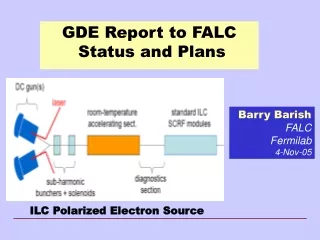
Funding Agencies for the Linear Collider • Seventh meeting held in Fermilab on 4 November 2005 • Representatives from CERN (President of Council and DG), Canada (NRC), France (CNRS), Germany (BMBF), Italy (INFN), Japan (MEXT), Korea (MOST), UK (PPARC) and the US (DOE) was held in Fermilab on 4 Nov 05 • The Group agreed that a Common Fund should be established to fund the administrative support required for the GDE ‘Phase-1’, with the costs to be funded equally by the three regions. The Group agreed that the use of this method of funding would not be used to prejudge the basis of any future agreements. It should only be applicable for the duration of this Common fund MOU for ‘Phase-1’. This Common Fund would be administered by Fermilab and be the subject of a MOU to be agreed by the FALC Resources group SLAC SPC
Funding Agencies for the Linear Collider • The Group discussed the need to minimize duplication of reporting and increase communication between the current project structure and FALC. The Chairs of ICFA and ILCSC were invited to attend future meetings of the Group and the Chair of ILCSC was invited to attend future meetings of the FALC Resources Group. • It was agreed that a subgroup, consisting of members of FALC from all three regions, would consider the future mandate of FALC, its composition, the relationship with existing bodies required as the project moved to a more formal governance structure and mechanisms by which funds could be made available both before and after a site decision. • It was agreed that the next meeting would be held on 22 May 2006 in Rome. SLAC SPC
Creating an International Project • Several Studies and Plans for ILC • ECFA EUROPEAN COMMITTEE FOR FUTURE ACCELERATORS subcomittee EUROPEAN LINEAR COLLIDER STEERING GROUP • “Report of the Sub-group on Organizational Matters” • Features a detailed breakdown of top level governance and project management, how they relate to each other. It is based on regional organizations; mostly in-kind contributions; shared central management, oversight, responsibility. It is concerned with Europe and how to do it within European Labs (CERN) and structures SLAC SPC
ECFA ILC Management Scheme SLAC SPC
Creating an International Project • Many models of International Collaboration • ITER is the largest project, shared by six countries. There are both lessons learned and models of how to develop international project with agreed to costing, shared management, etc. Siting was a big problem • ALMA is a joint European, U.S. and Japan project with a shared management, mostly in-kind contributions, etc. Being a big array, it is straight forward to divide how many modules are contributed by partners and siting is not an issue. But, they have recently dealt effectively with management and cost issues. SLAC SPC
2005 2006 2007 2008 2009 2010 Global Design Effort Project Baseline configuration Reference Design ILC Timeline …. Technical Design ILC R&D Program Expression of Interest to Host International Mgmt SLAC SPC