NETWORK SCHEDULING TECHNIQUES
NETWORK SCHEDULING TECHNIQUES. Network Diagrams. PMI defines the scheduling process as: “ the identification of the project objectives and the ordered activity necessary to complete the project including the identification of resource types and quantities required.”

NETWORK SCHEDULING TECHNIQUES
E N D
Presentation Transcript
Network Diagrams PMI defines the scheduling process as: “the identification of the project objectives and the ordered activity necessary to complete the project including the identification of resource types and quantities required.” Project scheduling defines the network logic for all activities that must either precede or succeed other tasks from the beginning of the project until its completion.
Network Diagrams Provide a basis for planning and how to use the resources Identify the critical path and project completion time Identify where slacks (float) are Reveal interdependencies of activities Aid in risk analysis (what-if analysis)
Network Diagrams Help schedule resources Show interdependence Show start & finish dates Facilitate communication Determine project completion Identify critical activities
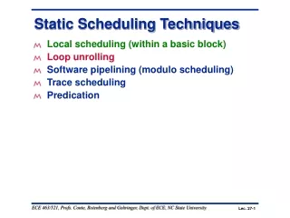
Network Scheduling Techniques Network scheduling techniques provide a logical process to consider the order in which the project activities should occur. The primary methods for developing project activity networks are: Program Evaluation and Review Technique (PERT) Critical Path Method (CPM) – Also called Arrow Diagram Method (ADM) Precedence Diagram Method (PDM)
Network Scheduling Techniques There are two ways to show the network: Activity-On-Node (AON) – nodes represent the activities Activity-On-Arch (AOA) – archs represent the activities AON is easier, and it used in commercial software.
E D B F C E D B F C AOA vs. AON activities on arc activities on node
PERT/CPM PERT was developed in the late 1950s in collaboration between the US Navy, Booz-Allen Hamilton and Lockeed Corporation for the creation of the Polaris missile program. CPM was developed at the same time by DuPont. Over the years the differences between PERT and CPM have blurred, so it is common to refer these techniques as just PERT/CPM.
Precedence Diagramming Method (PDM) PERT/CPM networks do not allow for leads and lags between two activities; i.e. a preceding activity must be completely finished before the start of the successor activity. Precedence Diagramming Method (PDM) allows these leads and lags. Most project management software systems use PDM and show interrelationships on bar charts.
Precedence Networkin a Gannt Chart MONTHS AFTER GO-AHEAD TASKS 1 2 3 4 5 1 2 3 4 5
Network Development Rules All activities must be linked to each other Network diagrams flow from left to right An activity cannot begin until all preceding connected activities have been completed Each activity should have a unique identifier (number, letter, code, etc.) Looping is not permitted It is common to start from a single beginning and finish on a single ending node
Steps in Creating the Network Define the project and all of its significant activities Develop the relationship among activities Decide which activities must precede others Draw the network connecting all of the activities Compute the longest path which is the critical path Calculate activity slacks (float) Use the network to help plan, schedule, and control the project
Node Labels Nodes representing activities should be labeled with the following information: Identifier Description Duration Early Start Time Early Finish Time Late Start Time Late Finish Time Float
Early Start ID Number Early Finish Activity Float Activity Descriptor Late Start Activity Duration Late Finish Node Labels
Node Labels Early Start (ES) – Earliest possible date an activity can start based on the network logic and any schedule constraints. Early Finish (EF) = ES + Dur Late Start (LS) – Latest possible date an activity may begin without delaying a specified milestone (usually project finish date). Late Finish (LF) = LS + Dur
B A D E F C Project Scheduling Terms • Merge activities • Burst activities • Node • Path • Critical Path • Successors • Predecessors • Network diagram • Serial activities • Concurrent activities
Project Scheduling Activities Serial activities flow from one to the next Concurrent activities are accomplished at the same time Merge activities have two or more immediate predecessor Burst activities have two or more successor activities
Merge Activities Activity A Activity B Activity D Activity C
Burst Activities Activity B Activity A Activity C Activity D
Activity Description Predecessors Duration A Contract signing None 5 B Questionnaire design A 5 C Target market ID A 6 D Survey sample B, C 13 E Develop presentation B 6 F Analyze results D 4 G Demographic analysis C 9 H Presentation to client E, F, G 2 Example
Example E Dev.Present. 6 B Design 5 A Contract 5 F Analysis 4 H Present 2 D Survey 13 C Market ID 6 G Demog. 9
Example Path One: A-B-E-H = 18 weeks Path Two: A-B-D-F-H = 29 weeks Path Three: A-C-D-F-H = 30 weeks Path Four: A-C-G-H = 22 weeks Path three is the critical path
Forward Pass Forward pass determines the earliest times (ES) each activity can begin and the earliest it can be completed (EF). There are three steps for applying the forward pass: Add all activity times along each path as we move through the network (ES + Dur = EF) Carry the EF time to the activity nodes immediately succeeding the recently completed node. That EF becomes the ES of the next node, unless the succeeding node is a merge point At a merge point, the largest preceding EF becomes the ES for that node (because the earliest the successor can begin is when all preceding activities have been completed)
5 B 10 Design 5 10 E 16 Dev. Present 6 Forward Pass 11 D 24 Survey 13 24 F 28 Analysis 4 28 H 30 Present 2 0 A 5 Contract 5 5 C 11 Market ID 6 11 G 20 Demog. 9 Activity D is a merge point for B and CActivity H is a merge point for E, F, and G
Backward Pass The goal of the backward pass is to determine each activity's Late Start (LS) and Late Finish (LF) times. There are three steps for applying the backward pass: Subtract activity times along each path through the network (LF – Dur = LS). Carry back the LS time to the activity nodes immediately preceding the successor node. That LS becomes the LF of the next node, unless the preceding node is a burst point. In the case of a burst point, the smallest succeeding LS becomes the LF for that node (because the latest the predecessor can finish is when any one of the successor activities should start)
10 E 16 Dev. Present 22 6 28 5 B 10 Design 6 5 11 Backward Pass 28 H 30 Presentation 28 2 30 0 A 5 Contract 0 5 5 24 F 28 Analysis 24 4 28 11 D 24 Survey 11 13 24 5 C 11 Market ID 5 6 11 11 G 20 Demograph. 19 9 28 Activities A, B, and C are burst points
Slack Time (Float) Since there exists only one path through the network that is the longest, the other paths must either be equal or shorter. Therefore, there are activities that can be completed before the time when they are actually needed. The time between the scheduled completion date and the required date to meet critical path is referred as the slack time. The activities on the critical path have zero slack time.
Slack Time (Float) The use of slack time provides better resource scheduling. It is also used as warning sign i.e. if available slack begins to decrease then activity is taking longer than anticipated. Slack time is equal to: LS – ES or LF – EF Activities on the critical path have 0 slack; i.e. any delay in these activities will delay the project completion.
5 B 10 1 Design 6 5 11 10 E 16 12 Dev. Present 22 6 28 Complete Activity Network 0 A 5 0 Contract 0 5 5 11 D 24 0 Survey 11 13 24 24 F 28 0 Analysis 24 4 28 28 H 30 0 Presentation 28 2 30 11 G 20 8 Demograph. 19 9 28 5 C 11 0 Market ID 5 6 11
Reducing the Critical Path • Eliminate tasks on the Critical Path • Convert serial paths to parallel when possible • Overlap sequential tasks • Shorten the duration on critical path tasks • Shorten • early tasks • longest tasks • easiest tasks • tasks that cost the least to speed up
Lag Lag is the time between Early Start or Early Finish of one activity and Early Start and Early Finish on another activity. For example, in a Finish-to-Start dependency with a 10-day lag, the successor activity cannot start until 10 days after the predecessor activity has finished. Lags are not the same as slacks. Lags are between activities whereas slacks are within activities.
0 A 6 Spec Design 6 6 B 11 Design Check 5 15 C 22 Blueprinting 7 Lag 4 Finish to Start Lag • Most common type of sequencing • Shown on the line joining the modes • Added during forward pass • Subtracted during backward pass This lag is not the same as activity slack
Lead Lead allows an acceleration of the successor activity. We can expedite the schedule by not waiting a preceding activity to be completely finished before starting its successor. For example, in a Finish-to-Start dependency with a 10-day lead, the successor activity can start 10 days before the predecessor activity has finished.
A(3) B(6) C(9) A1(1) A2(1) A3(1) B1(2) B2(2) B3(2) C1(3) C2(3) C3(3) Laddering Activities Project ABC can be completed more efficiently if subtasks are used (Fast Tracking) ABC=18 days Laddered ABC=12 days
0 A 5 0 5 5 • B 15 • 5 10 15 15 C 18 15 3 18 0 Hammock 18 0 18 18 Hammock Activities Used as summaries for subsets of activities Useful with a complex project or one that has a shared budget