Download
1 / 22
230 likes | 415 Views
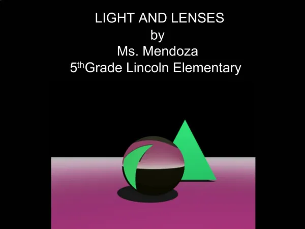
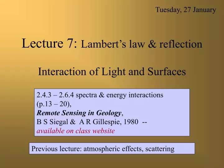
Tuesday, 27 January. Lecture 7: Lambert’s law & reflection Interaction of Light and Surfaces. 2.4.3 – 2.6.4 spectra & energy interactions (p.13 – 20), Remote Sensing in Geology , B S Siegal & A R Gillespie, 1980 -- available on class website.

E N D
Tuesday, 27 January Lecture 7: Lambert’s law & reflectionInteraction of Light and Surfaces 2.4.3 – 2.6.4 spectra & energy interactions (p.13 – 20), Remote Sensing in Geology, B S Siegal & A R Gillespie, 1980 -- available on class website Previous lecture: atmospheric effects, scattering
The amount of specular (mirror) reflection is given by Fresnel’s Law (n-1) 2 + K2 (n+1) 2 + K2 Light is reflected, absorbed , ortransmitted (RAT Law) rs Fresnel’s law rs = N = refractive index K = extinction coefficientfor the solid rs = fraction of light reflected from the 1st surface Mineral grain Absorption occurs here Transmitted component Beer’s law: (L = Lo e-kz) Snell’s law: n1·sin1 =n2·sin2 z = thickness of absorbing material k = absorption coefficient for the solid Lo = incoming directional radiance L = outgoing radiance Light passing from one medium to another is refracted according to Snell’s Law
Fresnel lens Augustin Fresnel Fresnel’s Law describes the reflection rs of light from a surface rs = ---------------- n is the refractive index K is the extinction coefficient (n -1)2 +K 2 (n+1)2 +K 2 This is the specular ray K is not the same as k, the absorption coefficient in Beer’s law (I = Io e-kz) (Beer – Lambert – Bouguer Law) K and k are related but not identical: k = --------- K is the imaginary part of the complex index of refraction: m=n-jK 4pK l
Complex refractive index n* = n + i k Consider an electrical wave propagating in the x direction: Ex=E0,x·exp[i·(kx·x·-ωt)] kx = component of the wave vector in the x direction = 2p/l; w = circular frequency =2pn; v=c/n* = n·λ; v = speed in light in medium; c = speed of light in vacuum; k=2p/l=w·n*/c Substituting, Ex = E0,x·exp[i·(w·(n+i·k)/c·x·-ω·t)] Ex = E0,x·exp[(i·w·n·x/c-w·k·x/c-i·ω·t)] Ex = E0,x·exp[-w·k·x/c]·exp[(i·(kx·x·-ω·t))] If we use a complex index of refraction, the propagation of electromagnetic waves in a material is whatever it would be for a simple real index of refraction times a damping factor (first term) that decreases the amplitude exponentially as a function of x. Notice the resemblance of the damping factor to the Beer-Lambert-Bouguer absorption law. The imaginary part k of the complex index of refraction thus describes the attenuation of electromagnetic waves in the material considered.
Surfaces may be - specular - back-reflecting - forward-reflecting - diffuse or Lambertian Smooth surfaces (rms<<l) generally are specular or forward-reflecting examples: water, ice Rough surfaces (rms>>l) generally are diffuse example: sand Complex surfaces with smooth facets at a variety of orientations are forward- or back-reflecting example: leaves Reflection envelopes
forward scattering diffuse reflection These styles of reflection from a surface contrast with scattering within the atmosphere Types of scattering envelopes Back scattering Forward scattering Uniform scattering
snow ski Forward scattering in snow Light escapes from snow because the absorption coefficient k in e-kz is small This helps increase the “reflectivity” of snow You can easily test this: observe the apparent color of the snow next to a ski or snowboard with a brightly colored base: What do you see?
Unit area Unit area The total irradiance intercepted by an extended surface is the same, but flux density is reduced by 1/cos i --- the total flux per unit area of surface is smaller by cos i How does viewing and illumination geometry affect radiance from Lambertian surfaces? Illumination I i I cos i i is the incident angle; I is irradiance in W m-2
How does viewing and illumination geometry affect radiance from Lambertian surfaces? Unresolved surface element exactly fills the IFOV at nadir, but doesn’t off nadir – part of the pixel “sees” the background instead Viewer at zenith Viewer at viewing angle e angular IFOV Same IFOV For a viewer off zenith, the same pixel is not filled by the 1 m2 surface element and the measured radiance is L = r p-1 I cosicos e therefore, point sources look darker as e increases 1 m2 Viewer at zenith sees r p-1 I cos i W sr-1 per pixel
How does viewing and illumination geometry affect radiance from Lambertian surfaces? Resolved surface element - pixels are filled regardless of e. Viewer at zenith Viewer at viewing angle e angular IFOV Same IFOV For a viewer off zenith, the same pixel now sees a foreshortened surface element with an area of 1/cos e m2 so that the measured radiance is L = r p-1 I cosi therefore, point sources do not change lightness as e increases 1 m2 Viewer at zenith still sees r p-1 I cos i W sr-1 per pixel
r p How does viewing and illumination geometry affect radiance from Lambertian surfaces? Reflection I i R= I cos i e I cos i i is the incident angle ; I is irradiance in W m-2 e is the emergent angle; R is the radiance in W m -2 sr-1
r p Lambertian Surfaces Specular ray I i i L= I cos i e I cos i i is the incidence angle; I is irradiance in W m-2 e is the emergence angle; L is the radiance in W m -2 sr-1 Specular ray would be at e=i if surface were smooth like glass
r p L= I cos i Lambertian Surfaces Rough at the wavelength of light Plowed fields The total light (hemispherical radiance) reflected from a surface is L = r I cos i W m -2 Lambertian surface - L is independent of e
the brightness of a snow field doesn’t depend on e, the exit angle DN=231 239 231 231 239 231 222
Reprise: reflection/refraction of light from surfaces (surface interactions) e Specular ray i i Incident ray Reflected light ° amount of reflected light = rI cosi ° amount is independent of view angle e ° color of specularly reflected light is essentially unchanged ° color of the refracted ray is subject to selective absorption ° volume scattering permits some of the refracted ray to reach the camera Refracted ray
r p Image intensity Effect of topography is to change incidence angle For topography elements >> l and >> IFOV i’ L= I cos i’ i This is how shaded relief maps are calculated (“hillshade”) Shadow
i’ i Variable shaded surfaces Shadowed Surface Shade vs. Shadow Shadow – blocking of direct illumination from the sun Shade – darkening of a surface due to illumination geometry. Does not include shadow. 29
Next we’ll consider spectroscopy fundamentals - what happens to light as it is refracted into the surface and absorbed - particle size effects - interaction mechanisms Light enters a translucent solid - uniform refractive index Light enters a particulate layer - contrast in refractive index
Surface/volume ratio = lower Light from coarsely particulate surfaces will have a smaller fraction of specularly reflected light than light from finely particulate surfaces Surface/volume ratio = higher
Obsidian Spectra Finest Reflectance Coarsest (Rock) Wavelength (nm) mesh Rock 16-32 32-42 42-60 60-100 100-150 150-200
Next lecture: 1) reflection/refraction of light from surfaces (surface interactions) 2) volume interactions - resonance - electronic interactions - vibrational interactions 3) spectroscopy - continuum vs. resonance bands - spectral “mining” - continuum analysis 4) spectra of common Earth-surface materials