Download
1 / 11
110 likes | 218 Views
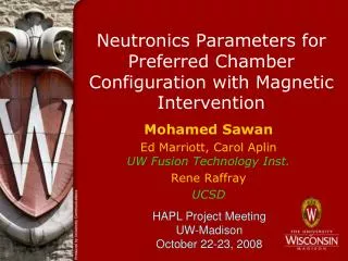
Shielding Requirements for Flibe/SiC Blanket with Magnetic Intervension Mohamed Sawan Fusion Technology Institute University of Wisconsin, Madison, WI HAPL Meeting UCSD January 30, 2007. Polar Cusp Armored Dump. Upper Blanket (single module). Upper-mid Blanket (16 modules). Magnets.

E N D
Shielding Requirements for Flibe/SiC Blanket with Magnetic Intervension Mohamed SawanFusion Technology InstituteUniversity of Wisconsin, Madison, WIHAPL MeetingUCSDJanuary 30, 2007
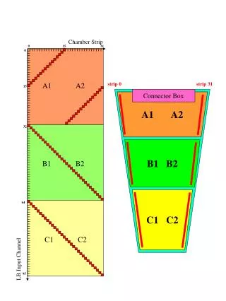
Polar Cusp Armored Dump Upper Blanket (single module) Upper-mid Blanket (16 modules) Magnets Shield/VV (50 cm thick) Lower-mid Blanket Ring Cusp Armored Dump Lower Blanket Chamber Configuration
Design Requirements for SS/water Shield • End-of-life (40 FPY) peak He production at back of shield/VV <1 He appmto allow for rewelding • Peak fast neutron fluence in magnets is limited to 1019 n/cm2 (E>0.1 MeV)due to degradation in Jc of superconductor • Peak dose in magnet insulator is limited to 1010 Radsdue to degradation of mechanical properties
Radiation Damage in Shield • A 50 cm thick steel (316SS or FS) shield that doubles as VV is used with 25% water cooling • Largest damage occurs at location with thinnest blanket • Peak end-of-life radiation damage in shield is only ~1 dpa lifetime component • He production in 316SS shield is ~ an order of magnitude higher than in FS • Back of the shield/VV is reweldable • If FS is used rewelding is possible at locations at least 10 cm deep in shield. If 316SS is used rewelding is possible at locations at least 20 cm deep in shield
Peak Damage Parameters in Superconducting Cusp Coils • 316SS shield provides slightly better magnet shielding • The cusp coils are well protected with the 50 cm shield (either FS or 316SS) • No restriction on location of the coils
Can We Have Personnel Access For Maintenance Behind Shield/VV? • Hands-on access for maintenance behind the shield/VV is not a requirement (only remote handling) • In ITER the limited time hands-on criterion adopted is 100 microSv/h (10 mrem/h) two weeks after shutdown. This roughly corresponds to ~3x10⁶ n/cm2.s fast neutron flux • Fast neutron flux behind 50 cm shield/VV is 5x10⁸ n/cm2s • Using 80 cm shield/VV results in fast neutron flux of 106 n/cm2s behind it with possible hands-on maintenance • However: • Activation of thin beam duct could restrict access • Need to move magnets farther from chamber
Required Biological Shield • Biological dose rate during operation behind the 50 cm shield/VV is 1.5x10⁷ mrem/hr (1.2x10⁵ for 80 cm shield/VV) • A biological shield is required to allow operational personnel access • A biological shield (containment building) made of 70% concrete, 20% carbon steel C1020, 10% water used with inner surface at 20 m from target • ~1.5 thick biological shield is required behind the blanket and shield/VV to allow personnel access outside containment building during operation • Bio-shield required is only ~1m with 80 cm shield/VV • ~2.5 m thick concrete is required behind the beam ports to shield personnel from streaming neutrons
1 m shield M2 M3 1 m shield 2.5 m Flux (n/cm2s) SiC GIMM 5 m Proposed Shield Modification at Final Optics of HAPL Acceptable operational dose rate of 1 mrem/h corresponds to ~10 n/cm2s fast neutron flux ~25 cm of concrete shield gives an order of magnitude flux attenuation
DIMENSIONS (cm) 550 1300 1450 550 Belt Dump: Duck bill plates 3 m long 150 cm at throat 125 cm FLIBE behind VERY PROVISIONAL 1625 Poloidal Dump: Cylinder plus dome 3 m long 75 cm radius 125 cm FLIBE behind VERY PROVISIONAL 125 blanket behind dump 10 m @ 200%: 1 mm = 1 m New Proposal (1/23/07)
Main Proposed Dimensions • 125 cm Flibe/SiC blanket (assumed uniform) • 20 cm SS/water magnet shield • 10 cm SS/water VV • 150 cm concrete bio-shield
Expected Nuclear Environment and Relation to Design Requirements • Local TBR in blanket 1.205 • OK • Peak radiation levels in magnets • fast neutron fluence 4.3x10¹⁷ n/cm2 • insulator dose 2.4x10⁹ Rads • OK • Peak He production in VV • 316SS 0.6 appm • FS 0.02 appm • OK • Operational dose rate behind bio-shield 8.3 mrem/h • 1.8 m bio-shield needed