Download
1 / 18
180 likes | 389 Views
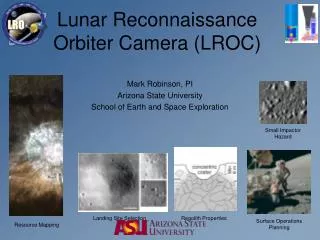
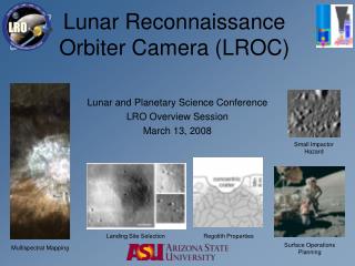
Lunar Reconnaissance Orbiter Camera (LROC). Small Impactor Hazard. Lunar and Planetary Science Conference LRO Overview Session March 13, 2008. Landing Site Selection. Regolith Properties. Surface Operations Planning. Multispectral Mapping. LROC Objectives.

E N D
Lunar ReconnaissanceOrbiter Camera (LROC) Small Impactor Hazard Lunar and Planetary Science Conference LRO Overview Session March 13, 2008 Landing Site Selection Regolith Properties Surface Operations Planning Multispectral Mapping
LROC Objectives 1. Sub-meter resolution imaging to select landing sites 2. Repeat imaging (100 m/pixel) of poles to identify regions of permanent shadow and (nearly?) continuous illumination 3. Half meter scale mapping of polar regions with (nearly?) continuous illumination 4. Overlapping observations to enable derivation of meter-scale topography 5. Global multispectral imaging for mineralogy and resource identification 6. Global morphology base map with high quality control 7. Characterize regolith (lunar soil) properties 8. Determine current impact hazard by re-imaging Apollo era images to count new craters SCS NAC WAC
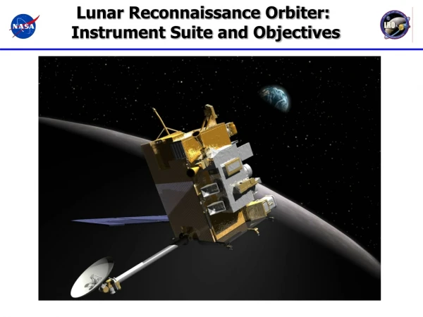
LROC Instrument Overview • Two Narrow Angle Cameras (NACs) for Landing Site Certification (50 cm/pixel) • One Wide Angle Camera (WAC) to Monitor Polar Lighting and Map Resources (100 m/pixel) WAC NAC
1. Landing Site Selection • Hundreds of potential sites imaged at 0.5 meter/pixel • Unambiguous identification of meter sized hazards • blocks • small craters • 5000 meter wide coverage with two NACs • Plus derived topography Apollo 15 set down on the rim of a small crater, damaging the engine bell and tilting at ~10°. LROC will help determine safe Landing sites.
2. Polar Illumination • WAC image of each pole every orbit over full year (time lapse movie) • Identify extent of permanently shadowed cold traps (potential volatile reservoirs) • Identify highly illuminated peaks - thermally benign landing sites (-53°C 10°C) Partial look at lunar north pole illumination from Clementine over 10 week period in summer (Bussey et al 2005). NAC: Summer - synoptic polar mapping, winter - repeat imaging highly illuminated peaks. -173°C to 116°C at lunar equator over a day (-280°F to 240°F)
3. Meter Scale Polar Mapping • NAC meter scale polar mapping (binned 2x for SNR and coverage), summer mosaics of each pole for morphology and permanent shadow analysis • Winter observations repeat coverage of highly illuminated peaks/ridges, capable of finding small regions of “perma-light” LROC NAC resolution at 1 m/pixel is 25x better than existing Clementine HIRES data.
4. High Resolution Topography • Stereo (3-D) coverage • Requires LRO to point off-nadir, easy at poles more difficult at equator • 5 meter (or better) stereo correlation patch • Photometric Stereo (3-D), multiple nadir observations of same region with varying lighting angles • Three or more images per site, 1 to 2 m/p topography • Very successful with NEAR images of Eros (Gaskell, JPL) • Directly supports landing site certification, and science investigations View of Apollo 17 site reconstructed from Apollo era high resolution topography
5. Global Multispectral Mapping • WAC UV / Visible • 315, 360, 415, 560, 600, 640, 680 nm bandpasses • Acquire global dataset at 100 m/pixel VIS, 400 m/pixel UV • Map TiO2 soils (hold H, He) • Pyroclastic glasses (volatiles) • Olivine Mg/Fe ratio (magmatic processes) • Anorthosite (origin of crust) Ilmenite Basalt LROC WAC bandpasses and key lunar mineral spectra (12063R Rock, 12070S Soil)
6. Global BW Basemap • Acquire 100 m/pixel high SNR global BW imaging, with optimal lighting for morphology • Key for establishing relative age dates through crater counting (ultimately absolute) • Enable accurate mapping of tectonic features • Also provide regional images of landing sites and resources Replace Clementine 100-200 m/p high Sun basemap (0-35° incidence at equator) with 100 m/pixel low Sun basemap (55-75° incidence angle at equator)
7. Regolith Characterization • Product of impacts: big, small, microscopic • Lots of time… • How thick? How blocky? • Small scale crater morphology Morphology indicates thickness Quaide and Oberbeck Method Each scene 119 m wide
8. Current Impact Rates Camelot • Critical measurement for understanding most dangerous impact hazards on Moon • Re-image Apollo Pan coverage at same lighting (high and low Sun) at 1 m/p • Should have been 900 (or more) craters >10 m/diameter formed since 1972 over whole Moon • Re-image 1% of Moon at 1 m/pixel - should find at least 9 craters according to current models Apollo 17 site in A17 Pan Frame 2314 (Camelot 600 m diameter - 1200 NAC pixels).
LROC Public Target • Request Webpage • Prototype • - Place a dual NAC • footprint on target • Enter confirmation e-mail • Target Name • Sun angle • Type keyword • Rationale • Submit
LROC Overview Backup Slides
Narrow Angle CameraNAC • 700 mm focal length, f/3.59, 2.86° FOV Richey-Chretien telescope (0.05 radian) • 5000 pixel line array detector (Kodak KLI 5001-G 7m pixels) • 0.5 meter/pixel at 50 km orbit (10 radian IFOV) • 2 NACs provide double the swath width (5000 m total), precision geometry and redundancy • SNR 40:1 worst case (2x binning at poles) • 7.6 kg, 8.8 W pk, 70 cm x 24 cm • System MTF 0.2
NAC StatusMarch 2008 • NAC Flight Unit 1 • Calibrated • Vibration complete • In TVAC for Focus Confirmation • Depart for GSFC ~March 25 • NAC Flight Unit 2 • End of thermal focus tests of telescope this week • Telescope delivery to MSSS expected ~March 18 • Calibration begins late March • Vibration • TVAC • Deliver GSFC April 15
NAC Flight Unit 1 Calibration Feb 2008
Wide Angle CameraWAC • Short focal length, FOV 90° Visible, 60° UV (1.57, 1.05 radian) • 1024 x 1024 pixel CCD (Kodak KAI 1001) • 100 m/pixel at 50 km orbit (1.57 mradian IFOV) • 7 filter bands (290 to 690 nm) • Global coverage with all 7 WAC bands, mesh with Clementine IR coverage (750 - 1000 nm) • 0.9 kg, 4 W, 15x9x8 cm • System MTF 0.3
WAC Status • First unit assembled • Calibration complete • Vibration Test Complete • In TVAC • Ship to GSFC March 25 • Second Unit awaiting new filter (and improved) filter assembly from Barr