Download
1 / 35
360 likes | 868 Views
Fundamentals of Liquid Cooling. Thermal Management of Electronics San Jos é State University Mechanical Engineering Department. PROS: Simplicity Low Cost Easy to Maintain Reliable. CONS: Inefficient at heat removal (low k and Pr ) Low thermal capacitance (low ρ and C p )

E N D
Fundamentals of Liquid Cooling Thermal Management of Electronics San José State University Mechanical Engineering Department
PROS: Simplicity Low Cost Easy to Maintain Reliable CONS: Inefficient at heat removal (low k and Pr) Low thermal capacitance (low ρ and Cp) Large thermal resistance Air as a Coolant
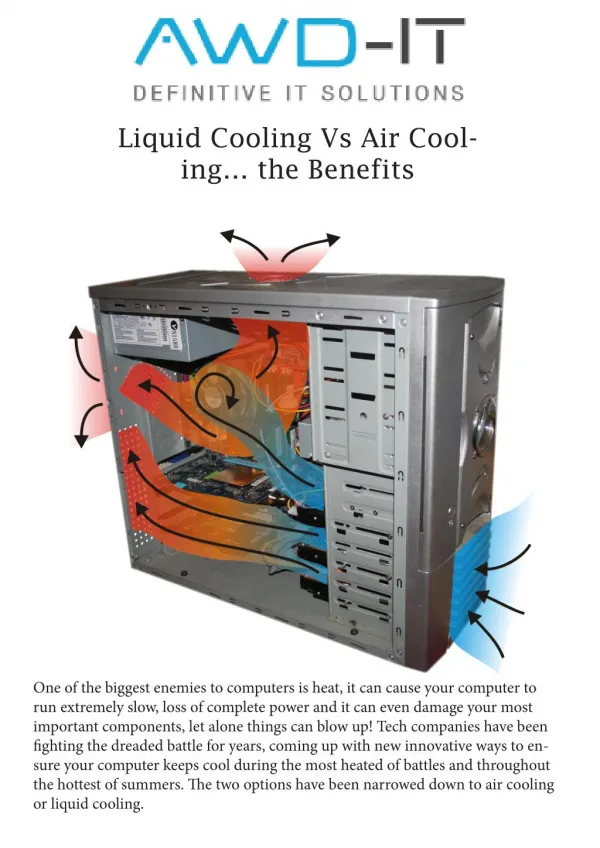
Using Alternate Coolants • As electronic components get smaller and heat transfer requirements increase air becomes a less efficient coolant • Liquid cooling provides a means in which thermal resistance can be reduced dramatically
Types of Liquid Cooling • Indirect – The coolant does not come into contact with the electronics. • Direct (Immersion) – The coolant is in direct contact with the electronics.
Fluid Selection • Is the fluid in direct contact with the electronics? • No. Water will normally be used due to the fact that it is cheap and has superior thermal properties. • Yes. A dielectric must be used. Consideration must be given to the thermal properties of different dielectric fluids.
Microchannels • Microchannels are most commonly used for indirect liquid cooling of IC’s and may be: • Machined into the chip itself. • Machined into a substrate or a heat sink and then attached to a chip or array of chips.
Microchannels • Example: Thermal Conduction Module used on IBM 3080X/3090 series • Heat is transmitted through an intermediate structure to a cold plate through which a coolant is pumped Incropera, pg. 3
Rth,h – Conduction Resistance through the chip Rth,c – Contact Resistance at the Chip/Substrate Interface Rth,sub – 3-D Conduction Resistance in the substrate (spreading resistance) Rth,cnv – Convection Resistance from the substrate to the coolant Microchannels Incropera, pg. 155 Note that this network ends with the mean fluid temperature. If we use the inlet fluid temperature, we also need to include Rcaloric
Motivating Example Laminar flow through a rectangular channel: Kandlikar and Grande, pg. 7 Kandlikar and Grande, pg. 8
Vis the mean flow velocity Lis the flow length ρ is the fluid density fis the friction factor, depends on the aspect ratio. Pressure Drop in Microchannels • The pressure drop due to forcing a fluid through a small channel may produce design limitations. • Limitations may include: • Pumping Power • Mechanical Stress Limitation of the Chip Material
Pressure Drop Example • If chip power increases mass flow rate must increase • If mass flow rate increases pressure drop increases Kandlikar and Grande, pg. 9
Optimization of Microchannels • How should the channels in the silicon substrate be designed for optimal heat transfer? Should the channel be deep or shallow? Make sure to give a valid reason. Kandlikar and Grande, pg. 9
Optimization of Microchannels • The channels should be deep so that the hydraulic diameter is small but the channel surface area is large. • Caution: Making the channels too small may result in unreasonable pressure drop. Kandlikar and Grande, pg. 9
Microchannel Issues • Liquids + Electronics • Self-explanatory • Fouling Leading to Clogging • Clogging prevents flow of liquids through a channel • Local areas where heat is not pulled away from components at a high enough rate are developed
Microchannel Issues • Mini-Pumps • Able to move liquid through the channel at a required rate • Able to produce large pressure heads to overcome the large pressure drop associated with the small channels • Tradition rotary pumps can not be used due to their large size and power consumption • For information on some current solutions refer to http://www.electronics-cooling.com/html/2006_may_a3.html
Current Research for Single Phase Convection in Microchannels • Surface Area • Adding protrusions to the channels to increase surface area. • Adding and arranging fins in a manner that is similar to a compact heat exchanger. Microstructures • Examples of different geometries: • Staggered Fins • Posts • T-Shaped Fins Silicon Substrate Kandlikar and Grande, pg. 10
Current Research for Single Phase Convection in Microchannels • Manufacturing Technology • Reducing cost of manufacturing • Producing enhanced geometries • For further information refer to article by Kandlikar and Grange
Current Research for Single Phase Convection in Microchannels • Justifying deviation from classical theory for friction and heat transfer coefficients when microchannel diameters become small • Lack of a good analytical model • Surface Roughness • Accurate measurements of system parameters • Ect. ***If you are interested in this take a look at: Palm, B. “Heat Transfer in Microchannels”. Microscale Thermophysical Engineering 5:155-175, 2001. Taylor Francis, 2001.
Jet Impingement • Benefits of using a jet in thermal management of a surface: • A thin hydrodynamic boundary layer is formed • A thin thermal boundary layer is formed Incropera, pg. 56
Jets can be: Free-Surface – discharged into an ambient gas Submerged – discharged into a liquid of the same type Cross Sections: Circular Rectangular Confinement: Confined – Flow is confined to a region after impingement Unconfined – Flow is unconfined after impingement Classifying Impinging Jets
Classify the Following Jets • Liquid jet released into ambient gas • Liquid release into liquid of the same type Incropera, pg. 56 Incropera, pg. 65
Classify the Following Jets • Unconfined, circular, free-surface jet • Unconfined, circular, submerged jet Incropera, pg. 56 Incropera, pg. 65
Nozzle Design • Nozzles are designed to create different jet characteristics • Example: Sufficiently long nozzles will produce both fully developed laminar or turbulent jets (Shown in b) Incropera, pg. 58
Flow Regions • Stagnation Region – Jet flow is decelerated normal to the impingement surface and accelerated parallel to it. Hydrodynamic and thermal boundary layers are uniform. • Wall Jet Region – Boundary layers begin to grow Incropera, pg. 62
Degradation of Heat Transfer During Jet Impingement • Splattering – Droplets are eject from the wall jet region due to the distance the nozzle is from the heat source and the surface tension of the jet fluid • Hydraulic Jump – An abrupt increase in film thickness and reduction in film velocity occurring in the wall jet region
Confining Fluid Flow • Adding a confining wall: • Adds low and high pressure regions • Sometimes adds secondary stagnation regions • Degrades convection heat transfer • Decreases space needed to use jet impingement Incropera, pg. 69
Two-Phase Boiling in Microchannels • Fluid entering microchannels is heated to the point where it boils • Flow in microchannels is highly unpredictable and can produce large voids and multiple flow regimes inside of tubes • No accurate analytical models currently exist; many analytical models have errors ranging from 10% to well over 100%
Flow Regimes in Two-Phase Applications Garimella, pg. 107
Immersion (Direct) Cooling • In direct cooling electronics are immersed into a dielectric liquid • Closed loop systems are normally used due to both the cost of the liquids used and the environmental issues associated with the liquids escaping into the atmosphere
Typical Liquids Used in Immersion Cengel, pg. 920
Boiling Used in Immersion Cengel, pg. 918 • Electronics expel heat into the liquid • Vapor bubbles are formed in the liquid • The vapor is collected at the top of the enclosure where it comes in contact with some sort of heat exchanger • The vapor condenses and returns to the liquid portion of the reservoir
Boiling Used in Immersion Cengel, pg. 919 • Electronics dissipate heat through the liquid • Vapor bubbles are generated • As vapor bubbles rise they come in contact with the cooler liquid produced by an immersed heat exchange and they implode *The prior example is more efficient due to the heat transfer coefficient associated with condensation
Cray-2 Supercomputer • Cold fluid enters between the circuit modules • Convection occurs, pulling heat from the electronics to the liquid • The heated fluid is pumped to a heat exchanger • Heat is transfer from the immersion liquid to chilled water in the heat exchanger Incropera, pg. 6
Concerns with Immersion • Introduction of incompressible gasses into a vapor space • This will limit the amount of condensation that is allowed to occur and degrade heat transfer • Leakage • Environmental Concerns • Reliability
Sources • Cengel, Yunus A. Heat Transfer: A Practical Approach. 1st edition. New York, NY: McGraw Hill. 1998 • Incropera, Frank P. Liquid Cooling of Electronic Devices by Single Phase Convection. Danvers, MA: John Wiley & Son. 1999 • Kandlikar, Satish G. and Grande, William J. “Evaluation of Single Phase Flow in Microchannels for High Heat Flux Chip Cooling – Thermohydrolic Performance Enhancement and Fabrication Technology”. Heat Transfer Engineering. Taylor Francis Inc. 25(8). 2004 • Palm, Bjorn. “Heat Transfer in Microchannels”. Microscale Thermophysical Engineering 5:155-175, 2001. Taylor Francis, 2001. • Kandlikar, Satish G. and Grande, William J. “Condensation Flow Mechanisms in Microchannels: Basis for Pressure Drop and Heat Transfer Models”. Heat Transfer Engineering. Taylor Francis Inc. 25(3). 2004