Download
1 / 47
580 likes | 1.2k Views
Telephone system. Structure of the Telephone System The Politics of Telephones The Local Loop: Modems, ADSL and Wireless Trunks and Multiplexing Switching. Public Switched Telephone Network.

E N D
Telephone system Structure of the Telephone System The Politics of Telephones The Local Loop: Modems, ADSL and Wireless Trunks and Multiplexing Switching
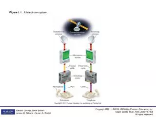
Public Switched Telephone Network • The PSTN (Public Switched Telephone Network), was designed many years ago, with one goal – to transmit the human voice in a more-or-less recognizable form • Its suitability for use in computer-computer communication is often marginal at best, but the situation is rapidly changing with the introduction of fiber optics and digital technology • Still, the telephone system is tightly intertwined with (wide area) computer networks
Cable versus dial-up lines • A cable running between two computers can transfer data at 109 bps, maybe more • A dial-up line has a maximum data rate of 56 kbps, a difference of a factor of almost 20,000 • With an ADSL connection, there is still a factor of 1000–2000 difference
Structure of the Telephone System • The initial market was for the sale of telephones, which came in pairs. It was up to the customer to string a single wire between them • Then came the single switching office • Then came the need to connect the switching offices • Scond-level switching offices were invented and after a while, multiple second-level offices were needed - the hierarchy grew to five levels
Structure of the Telephone System (a) Fully-interconnected network. (b) Centralized switch. (c) Two-level hierarchy.
The Telephone System • Each telephone has two copper wires coming out of it that go directly to the telephone company's nearest end office (also called a local central office) – distance 1 to 10 km, being shorter in cities than in rural areas • In the United States alone there are about 22,000 end offices • The two-wire connections between each subscriber's telephone and the end office are known in the trade as the local loop
The Telephone System • If a subscriber attached to a given end office calls another subscriber attached to the same end office, the switching mechanism within the office sets up a direct electrical connection between the two local loops and it remains intact for the duration of the call • Each end office has a number of outgoing lines to one or more nearby switching centers, called toll offices • The toll, primary, sectional, and regional exchanges communicate with each other via high-bandwidth intertoll trunks
Structure of the Telephone System A typical circuit route for a medium-distance call
The Telephone System • Local loops consist of category 3 twisted pairs • Between switching offices, coaxial cables, microwaves, and especially fiber optics are widely used • In the past, transmission throughout the telephone system was analog, with the actual voice signal being transmitted as an electrical voltage from source to destination • Nowadays all the trunks and switches are digital, leaving the local loop as the last piece of analog technology in the system
The Telephone System • Digital transmission is preferred because it is able to correctly distinguish a 0 from 1 which makes digital transmission more reliable than analog; it is also cheaper and easier to maintain • In summary, the telephone system consists of three major components: • Local loops (analog twisted pairs going into houses and businesses). • Trunks (digital fiber optics connecting the switching offices). • Switching offices (where calls are moved from one trunk to another).
The Local Loop: Modems, ADSL, and Wireless The use of both analog and digital transmissions for a computer to computer call. Conversion is done by the modems and codecs (compressor/decompressor)
The Local Loop • When a computer wishes to send digital data over an analog dial-up line, the data must first be converted to analog form for transmission over the local loop • The conversion is done by modem - modulator-demodulator – a device that accepts a serial stream of bits as input and produces a carrier modulated by one (or more) methods (or vice versa – accepts modulated carrier and produces serial stream of bits) • At the telephone company end office the data are converted to digital form for transmission over the long-haul trunks
The Local Loop • Transmission lines suffer from three major problems: attenuation, delay distortion, and noise • Attenuation - the loss of energy of the signal during its propagation • Delay distortion - the different Fourier components propagate at different speeds in the wire • Noise - unwanted energy from sources other than the transmitter
Modems and modulations • As the square waves used in digital signals have a wide frequency spectrum and are subject to strong attenuation and delay distortion, DC (Direct Current) signaling is unsuitable except at slow speeds and over short distances, so AC (Alternating Current) signaling is used • With AC signaling, a continuous tone in the 1000 to 2000-Hz range, called a sine wave carrier, is introduced. Its amplitude, frequency, or phase can be modulated to transmit information
Modems and modulations • In amplitude modulation, two different amplitudes are used to represent 0 and 1, respectively • In frequency modulation, two (or more) different tones are used. • In the simplest form of phase modulation, the carrier wave is systematically shifted 0 or 180 degrees at uniformly spaced intervals. A better scheme is to use shifts of 45, 135, 225, or 315 degrees to transmit 2 bits of information per time interval.
Modulations (a) A binary signal (b) Amplitude modulation (c) Frequency modulation (d) Phase modulation
Other modulations • For higher speeds, it is not possible to just keep increasing the sampling rate - even with a perfect 3000-Hz line (Nyquist theorem), there is no point in sampling faster than 6000 Hz • Most modems sample 2400 times/sec and focus on getting more bits per sample • The number of samples per second is measured in baud - for each baud, one symbol is sent • n-baud line transmits n symbols/sec- for example, a 2400-baud line sends one symbol about every 416.667 µsec
Baud rate and bit rate • Baud rate is the number of time a line changes per second • Example: • If Baud rate = 4 – this means that there will be 4 changes per second • If the number of bits per line change are 2 • => the bit rate = 8bps • If we have amplitude modulation – 4 levels – 00, 01, 10 and 11 level (similar for phase mod), or 4 tones (frequency modulation)
Other modulations • If the symbol consists of 0 volts for a logical 0 and 1 volt for a logical 1, the bit rate is 2400 bps • If voltages 0, 1, 2, and 3 volts are used, every symbol consists of 2 bits, so a 2400-baud line can transmit 2400 symbols/sec at a data rate of 4800 bps • With four possible phase shifts, there are also 2 bits/symbol, so again here the bit rate is twice the baud rate – i.e. 9600 bps • Widely usedtechnique - QPSK (Quadrature Phase Shift Keying)
Bandwidth, baud rate, bit rate • Bandwidth of a medium is the range of frequencies that pass through it with minimum attenuation • a physical property of the medium (usually from 0 to some maximum frequency) and measured in Hz • The baud rate - number of samples/sec (symbols/sec) made - each sample sends one piece of information (one symbol) • The modulation technique (e.g., QPSK) determines the number of bits/symbol • The bit rate is the amount of information sent over the channel and is equal to the number of symbols/sec times the number of bits/symbol(can be 2, 4, 8, 16… times the baud rate but also less - Manchester coding has a bit rate equal to 1/2 the baud rate)
QPSK • All advanced modems use a combination of modulation techniques to transmit multiple bits per baud - multiple amplitudes and multiple phase shifts are combined to transmit several bits/symbol • In next slide we see dots at 45, 135, 225, and 315 degrees with constant amplitude (distance from the origin) • The phase of a dot is indicated by the angle a line from it to the origin makes with the positive x-axis – first figure has four valid combinations and can be used to transmit 2 bits per symbol – a QPSK (Quadrature Phase Shift Keying)
Modulations (a) QPSK. (b) QAM-16. (c) QAM-64.
QAM-16 • In the second figure we see a modulation scheme, in which four amplitudes and four phases are used, for a total of 16 different combinations • Can transmit 4 bits per symbol - QAM-16 (Quadrature Amplitude Modulation) • Sometimes the term 16-QAM is used instead. QAM-16 can be used, for example, to transmit 9600 bps over a 2400-baud line
QAM-64 • At the third figure another modulation scheme involving amplitude and phase is used • It allows 64 different combinations, so 6 bits can be transmitted per symbol. It is called QAM-64. Higher-order QAMs also are used • Diagrams which show the legal combinations of amplitude and phase, are called constellationdiagrams • Each high-speed modem standard has its own constellation pattern and can talk only to other modems that use the same one (although most modems can emulate all the slower ones)
Extra bits for error correction • With many points in the constellation pattern, even a small amount of noise in the detected amplitude or phase can result in an error and, potentially, many bad bits • For less errors, standards for the higher speeds modems do error correction by adding extra bits to each sample • The schemes are known as TCM (Trellis Coded Modulation) - for example, the V.32 modem standard uses 32 constellation points to transmit 4 data bits and 1 parity bit per symbol at 2400 baud to achieve 9600 bps with error correction • Its constellation pattern is shown in the next slide (a) • ''rotating'' around the origin by 45 degrees is done for engineering reasons - rotated and unrotated constellations have the same information capacity
V.32 Modulations (a) V.32 for 9600 bps. (b) V32 bis for 14,400 bps. (b) (a)
V.32 bis • The next step above 9600 bps is 14,400 bps. It is called V.32 bis • 14.4Kbps is achieved by transmitting 6 data bits and 1 parity bit per sample at 2400 baud • V.32 bis’s constellation pattern has 128 points when QAM-128 is used • Fax modems use this speed to transmit pages that have been scanned in as bit maps • QAM-256 is not used in any standard telephone modems, but it is used on cable networks
V.34 and V.34 bis • The next telephone modem after V.32 bis is V.34, which runs at 28,800 bps at 2400 baud with 12 data bits/symbol • Another modem in this series is V.34 bis which uses 14 data bits/symbol at 2400 baud to achieve 33,600 bps • To increase the effective data rate further - modems compress the data before transmitting it, to get an effective data rate higher than 33,600 bps • Nearly all modems test the line before starting to transmit user data, and if they find the quality lacking, cut back to a speed lower than the rated maximum
Modems - modes • All modern modems allow traffic in both directions at the same time (by using different frequencies for different directions) • A connection that allows traffic in both directions simultaneously is called full duplex • A connection that allows traffic either way, but only one way at a time is called half duplex • A connection that allows traffic only one way is called simplex
Modems - V.90, V.92 • The number of bits per sample in the U.S. is 8, one of which is used for control purposes, allowing 56,000 bit/sec of user data • In Europe, all 8 bits are available to users, so 64,000-bit/sec modems could have been used, but as a standard - 56,000 was chosen • This modem standard is called V.90. It provides for a 33.6-kbps upstream channel (user to ISP), but a 56 kbps downstream channel • The next step is V.92 - capable of 48 kbps on the upstream channel if the line can handle it
Digital Subscriber Lines • Telephone companies needed a more competitive product to match cable TV operators • Services with more bandwidth than standard telephone service are sometimes called broadband • The most popular of these services is ADSL (Asymmetric Digital Subscriber Line)
Digital Subscriber Lines • The reason that modems are so slow is that telephones were for carrying the human voice – system is optimized for this purpose, not for data • At the point where each local loop terminates in the end office, the wire runs through a filter that attenuates all frequencies below 300 Hz and above 3400 Hz
ADSL • When a customer subscribes to ADSL, the incoming line is connected to a different kind of switch, one that does not have this filter, thus making the entire capacity of the local loop available • The limiting factor then becomes the physics of the local loop, not the artificial 3100 Hz bandwidth created by the filter
ADSL • Design goals: • - must work over the existing category 3 twisted pair local loops • - must not affect customers' existing telephones and fax machines • - must be much faster than 56 kbps • - should be always on, with just a monthly charge but no per-minute charge
ADSL • ADSL uses an approach called Discrete MultiTone (DMT) • the available 1.1 MHz spectrum on the local loop is divided into 256 independent channels of 4312.5 Hz each • Channel 0 is used for POTS (Plain Old Telephone Service) • Channels 1–5 are not used, to keep the voice and data from interfering • 250 channels remain - one is used for upstream control, one is used for downstream control and the rest are available for user data
Digital Subscriber Lines Operation of ADSL using discrete multitone modulation
ADSL • A 50–50 mix of upstream and downstream is technically possible, but most providers allocate something like 80%–90% of the bandwidth to the downstream • This choice gives rise to the ''A'' in ADSL • A common split is 32 channels for upstream and the rest downstream • The ADSL standard (ANSI T1.413 and ITU G.992.1) allows speeds of as much as 8 Mbps downstream and 1 Mbps upstream
ADSL • Within each channel, a modulation scheme similar to V.34 is used, although the sampling rate is 4000 baud instead of 2400 baud • The line quality in each channel is constantly monitored and the data rate adjusted continuously as needed, so different channels may have different data rates • The actual data are sent with QAM modulation, with up to 15 bits per baud, using a constellation diagram analogous to QAM-16
ADSL • A typical ADSL arrangement is shown in the following figure (after 1 slide) • There is a NID (Network Interface Device) on the customer's premises • Close to the NID (or sometimes combined with it) is a splitter, an analog filter that separates the 0-4000 Hz band used by POTS from the data
ADSL • The POTS signal is routed to the existing telephone or fax machine, and the data signal is routed to an ADSL modem - it is a digital signal processor that has been set up to act as 250 QAM modems operating in parallel at different frequencies • Most ADSL modems are external, the computer is connected to it at high speed - by putting an Ethernet card in the computer and operating a very short two-node Ethernet containing only the computer and ADSL modem
Digital Subscriber Lines A typical ADSL equipment configuration.
ADSL • At the other end of the wire, a corresponding splitter is installed • In it, the voice portion of the signal is filtered out and sent to the normal voice switch • The signal above 26 kHz is routed to a device called a DSLAM (Digital Subscriber Line Access Multiplexer), which contains the same kind of digital signal processor as the ADSL modem • Once the digital signal has been recovered into a bit stream, packets are formed and sent off to the ISP
ADSL • ADSL initially existed in two versions: • - CAP (Carrierless amplitude phase modulation), which is a variant of quadrature amplitude modulation (QAM) • - DMT (discrete multi-tone modulation) – identical to Orthogonal frequency-division multiplexing (OFDM), a frequency-division multiplexing (FDM) scheme used as a digital multi-carrier modulation method • ADSL2 provides downstream rate of 12MBps, upstream rate of 3.5 MBps • ADSL2+M provides downstream rate of 24MBps and upstream rate of 3.3 MBps
Wireless Local Loops • Fixed wireless (local telephone and Internet service run by provider over wireless local loops) - a fixed telephone using a wireless local loop is a bit like a mobile phone, but with three crucial technical differences • 1) the wireless local loop customers want high-speed Internet connectivity, often at speeds at least equal to ADSL • 2) they do not mind having installed a large directional antenna on roof pointed at the provider’s end office • 3) they do not move, eliminating all the problems with mobility and cell handoff (later studied)
Wireless Local Loops • FCC (Federal Communications Commission) allocated two television channels (at 6 MHz each) for instructional television at 2.1 GHz in 1969, in subsequent years, 31 more channels were added at 2.5 GHz for a total of 198 MHz • Instructional television never took off and in 1998, the FCC took the frequencies back and allocated them to two-way radio, which were immediately seized upon for wireless local loops – the service was called MMDS (Multichannel Multipoint Distribution Service) - microwaves have a range of about 50 km and can penetrate vegetation and rain moderately well • Later FCC also allocated 1.3 GHz to a new wireless local loop service called LMDS (Local Multipoint Distribution Service) – range 2-5 km
Wireless Local Loops Architecture of an LMDS system.
Wireless Local Loops • Like ADSL, LMDS uses an asymmetric bandwidth allocation favoring the downstream channel • To keep delays reasonable, no more than 9000 active users should be supported • With four sectors, as shown in the slide above, an active user population of 36,000 could be supported, so one can estimate, that a single tower with four antennas could serve 100,000 people within a 5-km radius of the tower • The standard by IEEE is 802.16 (2002) has been commercialized under the name “WiMAX” (from "Worldwide Interoperability for Microwave Access")