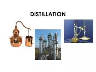
Continuous Column Distillation
Continuous Column Distillation. Column diagram. total condenser. • liquid/vapor streams inside the column flow counter-current in direct contact with each other. r eflux drum (accumulator). r eflux L, x R. d istillate D , x D.
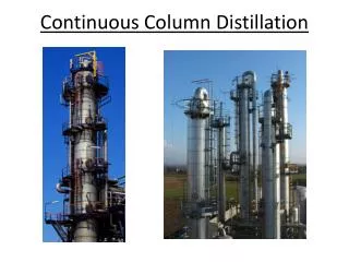

Continuous Column Distillation
E N D
Presentation Transcript
Column diagram total condenser • liquid/vapor streams inside the column flow counter-current in direct contact with each other reflux drum (accumulator) reflux L, xR distillate D, xD • all three external streams (F, D, B) can be liquids (usual case) enriching section • for a binary mixture, the compositions xF, xD, xBall refer to the more volatile component xR = xD feed F, xF feed stage yB≠xB temperature L V xD ≠ K xB stripping section • to keep the liquid flow rate constant, part of the distillate must be returned to the top of the column as reflux boilup V, yB bottoms B, xB • the partial reboiler is the last equilibrium stage in the system partial reboiler
External mass balance TMB:F = D + B CMB:F xF = D xD + B xB for specified F, xF, xD, xB, there are only 2 unknowns (D, B) distillate D, xD feed F, xF B = F - D bottoms B, xB
External energy balance • assume column is well-insulated, adiabatic EB: F hF + QC + QR = D hD+ B hB distillate D, xD feed F, xF F, hFare known D and B are saturated liquids sohD, hBare also known unknowns:QC, QR • need another equation bottoms B, xB
Balance on condenser vapor V1, y1 1. Mass balance TMB:V1 = D + L0 CMB:y1 = xD=xR(doesn’t help) unknowns: V1, L0 specify external reflux ratio R = L0/D V1= D + (L0/D)D = (1 + R)D 2. Energy balance V1H1 + QC = (D + L0)hD= V1hD QC = V1(hD – H1) then calculate QRfrom column energy balance reflux L0, xR distillate D, xD hD> H1 QC < 0 QR > 0
Splits Sometimes used instead of specifying compositions in product streams. What is the fractional recovery (FR) of benzene in the distillate? What is the fractional recovery (FR) of toluene in the bottoms? Most volatile component (MVC) is benzene: xF = 0.46
Calculating fractional recoveries B = F – D = 620 - 281 = 339
Stage-by-stage analysisLewis-Sorel method Consider the top of the distillation column: vapor V1, y1 V1, V2 are saturated vapors L0, L1 are saturated liquids reflux L0, x0 distillate D, xD stage 1 Which streams have compositions related by VLE? V1, L1 They are streams leaving the same equilibrium stage. K1(T1,P) = y1/x1 L1 x1 V2 y2 How are the compositions of streams V2and L1related? Need to perform balances around stage 1.
Relationships for stage 1 vapor V1, y1 TMB:L0 + V2 = L1 + V1 CMB:L0x0+ V2y2= L1x1+ V1y1 EB: L0h0+ V2H2= L1h1+ V1H1 VLE: K1(T1,P) = y1/x1 reflux L0, x0 distillate D, xD stage 1 There are 14 variables: 4 flow rates (L1, V2, L0, V1) 4 compositions (x1, y2, x0, y1) 4 enthalpies (h1, H2, h0, H1) T1, P We usually specify 10 of them: P, xD, D, R = L0/D xD= x0 = y1 V1 = L0 + D T1and all 4 enthalpies (by VLE) L1 x1 V2 y2 4 unknowns (L1, x1, V2, y2) and 4 equations: problem is completely specified.
Relationships for stage 2 TMB:L1 + V3 = L2 + V2 CMB:L1x1+ V3y3= L2x2+ V2y2 EB: L1h1+ V3H3= L2h2+ V2H2 VLE: K2(T2,P) = y2/x2 can solve for 4 unknowns (L2, x2, V3, y3) stage 2 L2,x2 V3,y3 and so on… proceed down the column to the reboiler. Very tedious. Simplifying assumption: If li (latent heat of vaporization) is not a strong function of composition, then each mole of vapor condensing on a given stage causes one mole of liquid to vaporize. Constant Molal Overflow (CMO): vapor and liquid flow rates are constant V2,y2 L1,x1
Constant molal overflow TMB: L1+ V3 = L2 + V2 CMO: V3 - V2= L2- L1 = 0 V3= V2= V L2= L1= L We can drop all subscripts on L and V in the upper section of the column (above the feed stage). internal reflux ratio: L/V = constant
Rectifying column Feed enters at the bottom, as a vapor. No reboiler required. Can give very pure distillate; but bottoms stream will not be very pure. Mass balance around top of column, down to and including stage j: L, xR D, xD stage j CMB: Vj+1yj+1= Ljxj+ DxD Lj,xj Vj+1,yj+1 CMO: yj+1= (L/V)xj+ (D/V) xD D = V - L yj+1 = (L/V)xj + (1 - L/V) xD F, xF B, xB Relates compositions of passing streams.
Lewis analysis of rectifying column • Assume CMO (Vj = Vj+1 = V; Lj = Lj-1 = L) • Need specified xD;xD = y1 • Stage 1: use VLE to obtain x1 x1 = y1/K1(T1,P) 4. Use mass balance to obtain y2 y2 = (L/V)x1 + (1 - L/V) xD 5. Stage 2: use VLE to obtain x2 x2 = y2/K2(T2,P) 6. Use mass balance to obtain y3 y3 = (L/V)x2 + (1 - L/V) xD 7. Continue until x = xB
Graphical analysis of rectifying column equation of the operating line: y = (L/V)x + (1 - L/V) xD slope = (L/V) always positive (compare to flash drum) VLE •xD = x0 (x0,y1) plotting the operating line: yint= (1 - L/V) xD op. line find a second point on the operating line: y = x = (L/V) x + (1 - L/V) xD = xD plot xD on y = x y=x yint• recall: xD = xR = x0; the passing stream is y1 • the operating line starts at the point (x0,y1) • the operating line gives the compositions of all passing streams (xj,yj+1)
McCabe-Thiele analysis: rectifying column • Plot VLE line (yi vs. xi) • Draw the y = x line • PlotxDon y = x • Plot yint= xD (1 – L/V) L/V internal reflux ratio, usually not specified instead, the external reflux ratio (R) is specified • Draw in the operating line • 6. Step off stages, alternating between VLE and operating line, • starting at (x0,y1) located at y = x = xD, until you reach x = xB • 7. Count the stages.
Ex.: MeOH-H2O rectifying column NEVER “step” over the VLE line. Rectifying column with total condenser Specifications: xD = 0.8, R = 2 Find N required to achieve xB = 0.1 VLE stage 1 (x1,y1)• •xD= x0 (x0,y1) stage 2 (x2,y2)• 1. Plot VLE line •(x1,y2) 2. Draw y=x line op. line 3. Plot xD on y=x (x3,y3)• stage 3 •(x2,y3) y=x 4. Plot yint = xD(1 - L/V) L/V = R/(R+1) = 2/3 yint = xD(1 - L/V)= 0.8/3 = 0.26 • yint• 5. Draw in operating line lowest xB possible for this op. line 6. Step off stages from xD to xB •xB 7. Count the stages N = 3
Limiting cases: rectification L/V = 1 Total reflux! L/V = 0 No reflux! Specifications: xD = 0.8, vary R = L/D VLE L 0 R = L/D 0 NO REFLUX L/V 0 stage 1 (x1,y1)• •xD= x0 (x0,y1) Column operates like a single equilibrium stage. (Why bother?) 0 ≤ R ≤ 0 ≤ L/V ≤ 1 y=x 2. D 0 R = L/D TOTAL REFLUX L/V = R/(R+1) 1 (L’Hôpital’s Rule) Operating line is y=x Max. distance between VLE and op. line Max. separation on each equil. stage Corresponds to Nmin, but no distillate!
Minimum reflux ratio L/V = 1 L/V = 0 Specifications: xD = 0.8, vary R Increasing R = L/D Decreasing D Decreasing xB (for fixed N) VLE •xD= x0 (x0,y1) • The number of stages N required to reach the VLE-op. line intersection point is . • • This represents xB,minfor a particular R. y=x • Rminfor this xB It also represents Rmin for this value of xB. 0 ≤ L/V ≤ 1 • xB ,min for this R 0 ≤ R ≤
Optimum reflux ratio total cost capital cost operating (energy) cost ∞ stages cost/lb min. heat required Ropt Rmin external reflux ratio, R Rule-of-thumb: 1.05 ≤Ropt/Rmin≤ 1.25 Ractual can be specified as a multiple of Rmin
Stripping column Feed enters at the top, as a liquid. No reflux required. Can give very pure bottoms; but distillate stream will not be very pure. Mass balance around bottom of column, up to and including stage k: D, xD CMB: Lk-1xk-1= Vkyk+ BxB Lk-1, xk-1 Vk,yk stage k CMO: yk= (L/V)xk-1- (B/V) xB L = V + B yk= (L/V)xk-1+ (1 - L/V) xB B, xB F, xF
Graphical analysis of stripping column equation of the operating line: y = (L/V)x + (1 - L/V) xB slope = L / V always positive VLE (xN+1,yN+1) PR • op. line plotting the operating line: y = x = (L/V) x + (1 - L/V) xB= xB plot xBon y = x y=x finding the operating line slope: = xN (xN+1,yN+2) •xB (recall V/B is the boilup ratio) Where is the partial reboiler? Designate this as stage N+1, with xN+1 = xB. Coordinates of the reboiler: (xN+1,yN+1)
McCabe-Thiele analysis: stripping column • Plot VLE line (yi vs. xi) • Draw the y = x line • PlotxBon y = x • Draw in the operating line • 5. Step off stages, alternating between VLE and operating line, • starting at (xN+1,yN+2) located at y = x = xB, until you reach x = xD • 6. Count the stages.
Ex.: MeOH-H2O stripping column NEVER step over the VLE line. (0.7,1) • Column with partial reboiler Specifications: xB = 0.07, Find N required to achieve xD = 0.55 VLE stage 1 (xN-2,yN-2) • • stage 2 •(xN-2,yN-2) (xN-1,yN-1) • stage 3 1. Plot VLE line • (xN-1,yN) (xN,yN) • 2. Draw y=x line op. line xD,max for this boilup ratio 3. Plot xB = xN+1 on y = x y=x 4. Draw op. line PR • • (xN,yN+1) (xN+1, yN+1) 5. Step off stages starting at PR xB= xN+1 • 6. Stop when you reach x = xD (xN+1,yN+2) xD • 7. Count the stages.
Limiting cases: stripping Specifications: xB = 0.07, vary boilup ratio VLE NO BOILUP Behaves as if the column wasn’t even there. (Why bother?) y=x 2. B 0 Operating line is y=x PR • TOTAL BOILUP TOTAL BOILUP xB= xN+1 • NO BOILUP Max. distance between VLE and op. line Max. separation on each equil. stage Corresponds to Nmin. But no bottoms product!
Increasing boilup ratio Decreasing B Increasing xD (for fixed N) Minimum boilup ratio No boilup Specifications: xB = 0.07, vary boilup ratio VLE The number of stages N required to reach the VLE-op. line intersection point is . yD ,max for this boilup ratio • • Total boilup This represents yD,maxfor a particular boilup ratio. • PR y=x • • It also represents the minimum boilup ratio for this value of yD. xB= xN+1 •
McCabe-Thiele analysis of complete distillation column Total condenser, partial reboiler Specifications: xD = 0.8, R = 2 xB = 0.07, Find N required Locate feed stage VLE Feed enters on stage 2 stage 1 •xD • stage 2 • • 1. Draw y=x line 2. Plot xD and xB on y=x y=x top op. line PR 3. Draw both op. lines • • 4. Step off stages starting at either end, using new op. line as you cross their intersection bottom op. line NEVER step over the VLE line. xB • 5. Stop when you reach the other endpoint 6. Count stages 7. Identify feed stage
Feed condition • Changing the feed temperature affects internal flow rates in the column feed F • If the feed enters as a saturated liquid, the liquid flow rate below the feed stage will increase: L V • If the feed enters as a saturated vapor, the vapor flow rate above the feed stage will increase: L V • If the feed flashes as it enters the feed stage to form a two-phase mixture, 50 % liquid, both the liquid and vapor flow rates will increase: and
Feed quality, q EB: rearrange: TMB: substitute: combine terms: q molsat’d liquid generated on feed plate, per mol feed define:
Different types of feed quality and saturated liquid feed q = 1 saturated vapor feed q = 0 feed flashes to form 2-phase 0 < q < 1 mixture, q% liquid subcooled liquid feed q > 1 - some vapor condenses on feed plate superheated vapor q < 0 - some liquid vaporizes on feed plate
Equation of the feed line rectifying section CMB: stripping section CMB: intersection of top and bottom operating lines: substitute: and equation of the feed line:
Plotting the feed line where does the feed line intersect y=x? VLE sat'dliq 2-phase subcooledliq y = x = zF sat'd vapor •zF superheated vap feed type q slope, m sat'd liquid q=1 m = sat'd vapor q=0 m = 0 2-phase liq/vap 0<q<1 m < 0 subcooledliq q>1 m > 1 superheated vap q<0 0<m<1 y=x
Ex.: Complete MeOH-H2O column Total condenser, partial reboiler Specifications: xD = 0.9, xB = 0.04, zF = 0.5, R=1 Feed is a 2-phase mixture, 50% liq. Find N and NF,opt. N = 6 + PR 1 •xD • 2 • 3 • 4 • 5 Operating lines intersect on stage 4. This isNF,opt. 1. Draw y=x line • • •zF 2. Plot xD, xB and zF on y=x 6 3. Draw feed line, slope = -0.5 y=x • 4. Draw top op. line, slope = L/V = 0.5 We can independently specify only 2 of the following 3 variables: R, q, V/B (usually: R, q). 5. Draw bottom op. line (no calc. required) PR xB • 6. Step off stages starting at either end, using new op. line as you cross the feed line. Using a non-optimal feed location reduces separation.
Feed lines in rectifying/stripping columns stripping column rectifying column •xD • yD • • • • • • • • • • top operating line • PR • • •xB bottom operating line xB • partial reboiler, no condenser sat’d liquid feed, vapor distillate F and V are passing streams total condenser, no reboiler sat’d vapor feed, liquid bottoms F and B are passing streams •zF • zF
Design freedom Fixed q. Vary R: Fixed R. Vary q: •xD •xD pinch point Rmin heat the feed decrease R qmin pinch point •zF •zF choice of R dictates required boilup ratio. • • xB xB You cannot “step” over a pinch point – this would require N = . It corresponds to a position in the column where there is no difference in composition between adjacent stages.
Another type of pinch point Ethanol-water xD = 0.82, xB = 0.07 zF = 0.5, q = 0.5 Find Rmin •xD pinch point 1. Draw y=x line VLE 2. Plot xD, xB and zF on y=x •zF 3. Draw feed line, slope = q/(q-1) y=x 4. Draw top op. line to intersect with feed line on VLE line 5. Don’t cross the VLE line! 6. Redraw top operating line as tangent to VLE. xB •
Additional column inputs/outputs Column with two feeds: Column with three products: distillate D, xD distillate D, xD feed 2 F2, z2, q2 side-stream S, xS or yS z2 > z1 and/or q2 > q1 L´ V´ L´ V´ feed F, z side-streams must be saturated liquid or vapor L L V V feed 1 F1, z1, q1 L V L V bottoms B, xB bottoms B, xB Each intermediate input/output stream changes the mass balance, requiring a new operating line.
Multiple feedstreams Total condenser, partial reboiler Specifications: xD = 0.9, xB = 0.07, z1 = 0.4, z2=0.6 Some specified q-values R = 1. Find N, NF1,opt, NF2,opt VLE 1 • •xD 2 • 3 • 4 • 1. Draw y=x line •z2 • 2. Plot xD, z1, z2 and xB on y=x 5 •z1 = z2 3. Draw both feed lines •z1 4. Draw top op. line, slope = L/V • 5. Calculate slope of middle operating line, L´/V´, and draw middle operating line PR y=x Optimum location for feed 1 is stage 5. Optimum location for feed 2 is stage 3. 6. Draw bottom operating line (no calc. required) • xB 7. Step off stages starting at either end, using new op. line each time you cross an intersection
Slope of middle operating line 2-feed mass balances: TMB: F2+ V´ = L´ + D CMB: F2z2 + V´yj+1 = L´xj + DxD middle operating line equation: y = (L´/V´)x + (DxD - F2z2)/V´ feed 2 F2, z2, q2 D, xD obtain slope from: L´ = F2q2 + L = F2q2 + (R)(D) V´ = L´ + D – F2 L´ L´ V´ V´ side-stream feed-stream with –ve flow rate sat’dliq y = x = xS sat’d vapor y = x = yS stage j stage j side-stream mass balances: TMB: V´- L´= D + S CMB: V´yj+1 - L´xj = DxD + SxS D, xD side-stream S, xS or yS middle operating line equation: y = (L´/V´)x + (DxD + SxS)/V´
McCabe-Thiele analysis of side-streams Saturated liquid side-stream, xs= 0.64 Saturated vapor side-stream, ys= 0.73 • • •xD •xD • • •yS • VLE VLE •xS •z •z y=x y=x xB xB • • Side-stream must correspond exactly to stage position.
Partial condensers A partial condenser can be used when a vapor distillate is desired: D, yD • •yD PC • 1 • 2 V, y1 L, x0 L V y=x A partial condenser is an equilibrium stage. CMB: Vyj+1= Lxj + DyD Operating line equation: y= (L/V)x + DyD= (L/V)x + (1 - L/V)yD
Total reboilers A total reboiler is simpler (less expensive) than a partial reboiler and is used when the bottoms stream is readily vaporized: • • N-1 stage N V L N V, yB B, xB y=x •xB,yB TR A total reboiler is not an equilibrium stage.
Stage efficiency Under real operating conditions, equilibrium is approached but not achieved: Nactual > Nequil overall column efficiency: Eoverall = Nequil/Nactual Efficiency can vary from stage to stage. Reboiler efficiency ≠ tray efficiency Murphreevapor efficiency: Can also define Murphreeliquid efficiency: where yn* is the equilibrium vapor composition (not actually achieved) on stage n: yn* = Knxn xj* = yj / Kj
Ex.: Vapor efficiency of MeOH-H2O column Total condenser, partial reboiler Specifications: xD = 0.9, xB = 0.07, z = 0.5, q = 0.5, R = 1, EMV,PR= 1, EMV = 0.75. Find N and NF,opt. 1 • • •xD • 2 • 3 • 4 • 5 • 1. Draw y=x line 7 6 2. Plot xD, z, and xB on y=x • •z 3. Draw feed line 8 4. Draw top op. line, slope = L/V y=x 5. Draw bottom operating line (no calc. required) N = 8 + PR PR • NF,opt = 6 6. Find partial reboiler 7. Step off stages, using EMV to adjust vertical step size. xB • 8. Label real stages. To use ELV, adjust horizontal step size instead.
Intermediate condensers and reboilers • Intermediate condensers/reboilers can improve the energy efficiency of column distillation: • by decreasing the heat that must be supplied at the bottom of the column, providing part of the heat using an intermediate reboiler instead • - use a smaller (cheaper) heating element at the bottom of the column, or lower temperature steam to heat the boilup • by decreasing the cooling that must be supplied at the top of the column, providing part of the cooling using an intermediate condenser instead • - use a smaller (cheaper) cooling element at the top of the column, and/or a higher temperature coolant for the intermediate condenser distillate D, xD feed F, z L´ L´´ V´´ V´ S, xS L V intermediate reboiler yS = xS L V bottoms B, xB Each column section has its own operating line.
Subcooled reflux If the condenser is located below the top of the column, the reflux stream has to be pumped to the top of the column. Pumping a saturated liquid damages the pump, by causing cavitation. The reflux stream (L0) should be subcooled. This will cause some vapor to condense. stage 1 c V1, y1 L0, x0 V1= V2 - c and L1 = L0 + c V2 CMO is valid below stage 1. Find L/V = L1/V2? EB: V2H2 + L0h0 = V1H1 + L1h1 where H1H2 = H, but h0 ≠ h1 = h (V2 – V1)H = L1h - L0h0 cH = (L0 + c)h - L0h0 = L0(h - h0) + ch L1 D, xD q0quality of reflux Subcooled reflux causes L/V to increase. Superheated boilup causes L/V to increase. where L0/V1 = (L0/D)/(1 + L0/D) = R/(R + 1)
Open steam distillation If the bottoms stream is primarily water, then the boilup is primarily steam. Can replace reboiler with direct steam heating (S). L, xR D, xD mostly MeOH Top operating line and feed lines do not change. Bottom operating line is different: MeOH/H2O feed F, z TMB: V + B = L + S stage j usually 0 CMB: V yj+1 + B xB = L xj + S yS mostly H2O Lj, xj Vj+1, yj+1 CMO: B = L bottoms B, xB Operating line equation: y= (L/V) x - (L/V) xB B, xB S, yS xint: x = xB
Ex.: Open steam distillation of MeOH/H2O Specifications: xD = 0.9, xB = 0.07, zF = 0.5 Feed is a 2-phase mixture, 50% liq. Total condenser, open steam, R = 1. Find N and NF,opt. VLE 1 • •xD 2 • 3 • 4 • 1. Draw y=x line 5 2. Plot xD and zF on y=x • •zF 3. Plot xB on x-axis 4. Draw feed line, slope = q/(q-1) y=x • 5. Draw top op. line, slope = L/V 6 All stages are on the column (no partial reboiler). 6. Draw bottom op. line (no calc. required) N = 6 NF,opt = 4 7. Step off stages starting at either end, using new op. line as you cross their intersection • xB
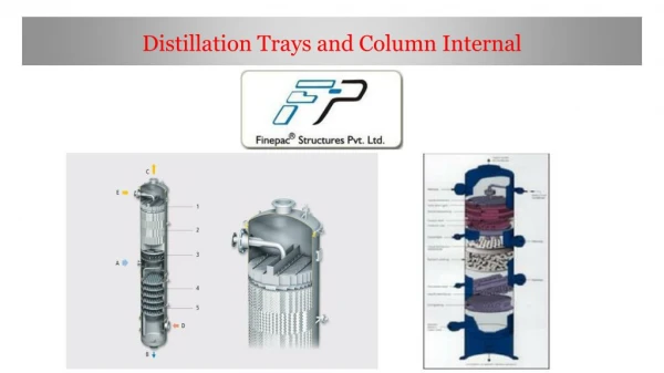
Column internals Sieve tray • Also called a perforated tray • Simple, cheap, easy to clean • Good for feeds that contain suspended solids • Poor turndown performance (low efficiency when operated below designed flow rate); prone to “weeping”
Other types of trays Valve tray Bubble cap tray • Some valves close when vapor velocity drops, keeping vapor flow rate constant • Better turndown performance • Slightly more expensive, and harder to clean than sieve tray • Excellent contact between vapor and liquid • Risers around holes prevent weeping • Good performance at high and low liquid flow rates • Very expensive, and very hard to clean • Not much used anymore