Download
1 / 20
200 likes | 327 Views
JTA1 Antenna-wire coupling in the near field Measurement results from ULg Ir. V. Beauvois ; Ir. M. Renard ; P. Beerten V.Beauvois@ulg.ac.be. Original problem. 1, 5, 10 m D l 1m. -30cm -> l +30cm D x = 5 cm. 3 m. 150 . 5 → 30/80 cm. 1,5 m. GND plane. 1 m. 12 m. V. H. 10 cm.

E N D
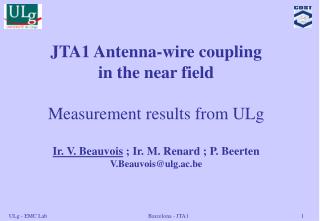
JTA1 Antenna-wire coupling in the near field Measurement results from ULg Ir. V. Beauvois ; Ir. M. Renard ; P. Beerten V.Beauvois@ulg.ac.be
Original problem 1, 5, 10 mDl 1m -30cm -> l +30cm Dx = 5 cm 3 m 150 5 → 30/80 cm 1,5 m GND plane 1 m 12 m V H 10 cm 10 cm
V H H // 10 cm 10 cm Position of the antenna used for simulation of a GSM phone
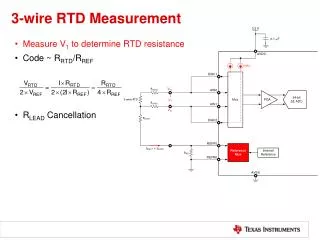
Wire Ø 1.78mm (2.5mm²) instead of 2mm ; • Equipments : • Generator SMY02 R&S at 13dBm 900MHz • EMI Receiver ESI26 R&S • RBW : 120kHz • m.t. : 1s • CR100 (100W) • Coaxial cables • “GSM” Antenna Kathrein ref. K71 166 1 • brass rod in plastic tube • Dipole (for reference) HZ-13 R&S tuned for 900MHz
100W Cable to spectrum 50W input 1m cable Ground plane
Measurement conditions : 1m cable 5cm, 10cm, 15cm, 20cm, 25cm, 30cm, 50cm, 80cm 5m cable 5cm, 10cm, 15cm, 30cm, 50cm, 80cm (time consuming) Longer cable : ground plane limit
*Some uncertainties : to be checked linked to cable attenuations
Still to be done: • to check some measurements • to check the values (cable attenuation) • to compare our values with • other measurements • simulations • influence of “site” (open site, anechoic room, • metal plate in environment)