Mextram 504 BJT model
Mextram 504 BJT model. F. Yuan Advisor : Prof. C. W. Liu Graduate Institute of Electronics Engineering and Department of Electrical Engineering, National Taiwan University, Taipei, Taiwan. Outline. Charge modeling Collector current Base current series resistance, epilayer resistance

Mextram 504 BJT model
E N D
Presentation Transcript
Mextram 504 BJT model F. Yuan Advisor: Prof. C. W. Liu Graduate Institute of Electronics Engineering and Department of Electrical Engineering, National Taiwan University, Taipei, Taiwan
Outline • Charge modeling • Collector current • Base current • series resistance, epilayer resistance • Avalanche multiplication • Extrinsic region • AC small-signal model • Noise and temperature effect
Depletion charge (Qte,Qtc) • Set Q=0 at V=0 • Change function to a smooth one to prevent the value become infinite at V=Vd
Base diffusion charge (QBE,QBC) • Injected , so we caculate injected e- • Define base charge at zero bias • QBE+QBC=all diffusion charge in base Assumed linear
Main current (IN) q1=1 means no early effect
Total base charge (qB) • Early effect (base width modulation) Qte,Qtc • High level injection QBE,QBC
Base current (IB1,IB2) • IB1 is ideal forward base current • IB2 is non-ideal forward base current (2kT current at low bias) • S means sidewall
SiGe HBT • qB is modified by the bandgap difference of the base region • Only considered the linear graded Ge profile • If there are a lot of defects in SiGe base, there is neutral base recombination current (1kT current)
Diffusion charge (QE, Qepi) • Emitter diffusion charge QE • Collector epilayer diffusion charge Qepi
Base capacitance • Base current is injected from side, the voltage on B1 and B2 may be different • We must compensate the charge
Base resistance • DC crowding effect B2 B B1 RBv RBc
Collector resistance • Buried layer to collector electrode resistance is constant RCC • Epilayer resistance is a variable
Collector resistance • When IC large, RC :small to high to small
Collector resistance • Kull, TED vol.32, no.6, p1103, 1985
Collector resistance • Jeroen, SSC vol.36, no.9, p1390, 2001 • Also considered the high current base push-out (Kirk effect) • Velocity saturation • Final equation is
RF performance • fT roll-off at high IC, IC1C2 is the key • When IC get large enough, base push-out occurs, increase and makes fT roll-off • Mextram model based on more physical parameters
Avalanche multiplication • Weak avalanche effect • Valid only for IC1C2 < Ihc • Kloosterman, p172, BCTM 2000
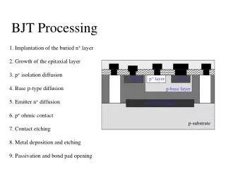
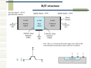
Extrinsic region • Base-SIC:intrinsic • Base-epilayer-buried layer:extrinsic • Base-(p-poly)-buried layer:external
Reverse base current (Iex,IB3) • Iex is ideal reverse base current • IB3 is non-ideal reverse base current (2kT current at low bias) • Xext is partitioning factor
Extrinsic region • External reverse base current, XIex • Extrinsic depletion charge, Qtex • External depletion charge, XQtex • Extrinsic diffusion charge, Qex • External diffusion charge, XQex
Parasitic PNP • Base-Collector-Substrate:parasitic PNP • Only for it’s main current
Others • Collector-Substrate depletion capacitance • Reverse substrate current • Constant B-E, B-C overlap capacitance
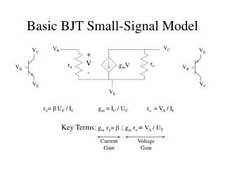
Small-signal equivalent circuit • x:VB2E1 • y:VB2C2 • z:VB2C1
Small-signal equivalent circuit • x:VB2E1 • y:VB2C2 • z:VB2C1
Small-signal equivalent circuit • x:VB2E1 • y:VB2C2 • z:VB2C1
Small-signal equivalent circuit • x:VB2E1 • y:VB2C2 • z:VB2C1
Small-signal equivalent circuit • x:VB2E1 • y:VB2C2 • z:VB2C1 • Can get more precise parameters • Extrinsic added
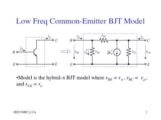
Hybrid-π model • Let the equivalent circuit has only One current source B2-E1-(C1-E1)=B2-C1
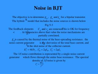
Noise (for AC) • Thermal noise -- consider variable resistance • Shot noise • Flicker noise (1/f noise) -- non-ideal base current use KfN
Temperature • Temperature rules are applied to various parameter • Self-Heating is considered
Comparison to GP • fT-IC is more accurate • Mextram parameters are base on more physical way • Noise is considered more accurate because the variable resistance • Linear graded SiGe HBT model in Mextram 504 • Weak avalanche breakdown
Still unconsidered • B-E junction breakdown • High injection current breakdown