Morphological Image Processing
Morphological Image Processing.

Morphological Image Processing
E N D
Presentation Transcript
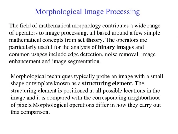
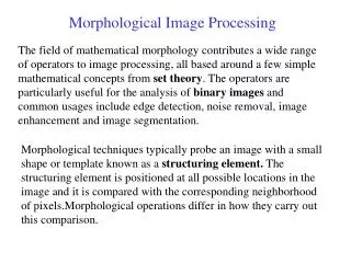
Morphological Image Processing The field of mathematical morphology contributes a wide range of operators to image processing, all based around a few simple mathematical concepts from set theory. The operators are particularly useful for the analysis of binary images and common usages include edge detection, noise removal, image enhancement and image segmentation. Morphological techniques typically probe an image with a small shape or template known as a structuring element. The structuring element is positioned at all possible locations in the image and it is compared with the corresponding neighborhood of pixels.Morphological operations differ in how they carry out this comparison.
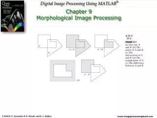
Some Basic Concepts from Set Theory If a=(a1,a2) is an element of A, then we write: a A If a is not an element of A , we write: a A The set with no elements is called the null or empty set and is denoted by the symbol . If every element of a set A is also an element of another set B, then a is said to be a subset of B, denoted as A B The union of two sets A and B, denoted by C=A B Is the set of all elements belonging to either A,B or both The intersection of two sets A and B, denoted by D=A B; Is the set of all elements belonging to both A and B Two sets A and B are said to be disjoint or mutually exclusive if they have no common elements.A B =
p q p AND q p OR q NOT p 0 0 0 0 1 0 1 0 1 1 1 0 0 1 0 1 1 1 1 0 Logical Operation Involving Binary Images The logical operations just descried have a one-to one correspondence with the set operations is set theory ( union , intersection ) with the limitation that logical operations are restricted to binary variables.
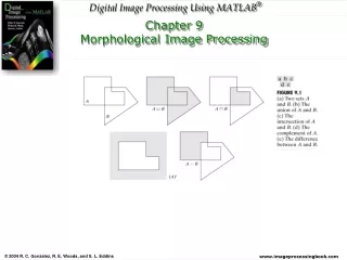
Fundamental Definitions We defined an image as an (amplitude) function of two, real (coordinate) variables a(x,y) or two, discrete variables a[m,n]. An alternative definition of an image can be based on the notion that an image consists of a set (or collection) of either continuous or discrete coordinates. In a sense the set corresponds to the points or pixels that belong to the objects in the image. This is illustrated in Figure which contains two objects or sets A and B. Note that the coordinate system is required. For the moment we will consider the pixel values to be binary. Figure : A binary image containing two object sets A and B.
Fundamental Definitions The object A consists of those pixels a that share some common property: Object - The background of A is given by Ac (the complement of A) which is defined as those elements that are not in A: Background -
Fundamental Definitions The fundamental operations associated with an object are the standard set operations union, intersection, and complement plus translation:
Fundamental Definitions The complement of A is the binary image which interchange the 1s and 0s in A . Thus, The intersection of any two binary images A and B , written A B, is the binary image which is 1 at all pixels p which are 1 in both A and B The intersection is computed by applying the rule: The union of A and B, written AB, is the binary image which is 1 at all pixels p which are 1 in A or 1 in B ( or in both)
Fundamental Definitions * Translation - Given a vector x and a set A, the translation, A + x, is defined as: Note that, since we are dealing with a digital image composed of pixels at integer coordinate positions (Z2), this implies restrictions on the allowable translation vectors x. The basic Minkowskisetoperations--addition and subtraction--can now be defined. First we note that the individual elements that comprise B are not only pixels but also vectors as they have a clear coordinate position with respect to [0,0]. Given two sets A and B: Minkowskiaddition - Minkowskisubtraction -
Fundamental Definitions – Erosion and Dilation From these two Minkowski operations we define the fundamental mathematical morphology operations dilation and erosion: Dilation - Erosion - where
Fundamental Definitions – Erosion and Dilation While either set A or B can be thought of as an "image", A is usually considered as the image and B is called a structuring element. The structuring element is to mathematical morphology what the convolution kernel is to linear filter theory. Dilation, in general, causes objects to dilate or grow in size; erosion causes objects to shrink. The amount and the way that they grow or shrink depend upon the choice of the structuring element. Dilating or eroding without specifying the structural element makes no more sense than trying to lowpass filter an image without specifying the filter.
Structuring Elements The structuring element is sometimes called the kernel, but we reserve that term for the similar objects used in convolutions. The structuring element consists of a pattern specified as the coordinates of a number of discrete points relative to some origin. Normally Cartesian coordinates are used and so a convenient way of representing the element is as a small image on a rectangular grid. Figure 1 shows a number of different structuring elements of various sizes. In each case the origin is marked by a ring around that point. The origin does not have to be in the center of the structuring element, but often it is. As suggested by the figure, structuring elements that fit into a 3×3 grid with its origin at the center are the most commonly seen type.
Structuring Elements Figure 1 Some example structuring elements.
Sstructuring Element Note that each point in the structuring element may have a value. In the simplest structuring elements used with binary images for operations such as erosion, the elements only have one value, conveniently represented as a one. More complicated elements, such as those used with thinning or grayscale morphological operations, may have other pixel values. The structuring element is already just a set of point coordinates (although it is often represented as a binary image). It differs from the input image coordinate set in that it is normally much smaller, and its coordinate origin is often not in a corner, so that some coordinate elements will have negative values. Note that in many implementations of morphological operators, the structuring element is assumed to be a particular shape (e.g. a 3×3 square) and so is hardwired into the algorithm.
Sstructuring Element The two most common structuring elements (given a Cartesian grid) are the 4-connected and 8-connected sets, N4 and N8. They are illustrated in Figure . Figure: The standard structuring elements N4 and N8.
Binary Images For a binary image, white pixels are normally taken to represent foreground regions, while black pixels denote background. (Note that in some implementations this convention is reversed, and so it is very important to set up input images with the correct polarity for the implementation being used). Then the set of coordinates corresponding to that image is simply the set of two-dimensional Euclidean coordinates of all the foreground pixels in the image, with an origin normally taken in one of the corners so that all coordinates have positive elements.
Gray Scale Images For a grayscale image, the intensity value is taken to represent height above a base plane, so that the grayscale image represents a surface in three-dimensional Euclidean space. Figure 2 shows such a surface. Then the set of coordinates associated with this image surface is simply the set of three-dimensional Euclidean coordinates of all the points within this surface and also all points below the surface, down to the base plane. Note that even when we are only considering points with integer coordinates, this is a lot of points, so usually algorithms are employed that do not need to consider all the points.
Fundamental Morphological Operations Erosion and dilation work (at least conceptually) by translating the structuring element to various points in the input image, and examining the intersection between the translated kernel coordinates and the input image coordinates. For instance, in the case of erosion, the output coordinate set consists of just those points to which the origin of the structuring element can be translated, while the element still remains entirely `within' the input image. Virtually all other mathematical morphology operators can be defined in terms of combinations of erosion and dilation along with set operators such as intersection and union. Some of the more important are opening, closing and skeletonization.
Fitting and Hitting When we place a structuring element in a binary image, each of its pixels is associated with the corresponding pixel of the neighborhood under the structuring element. In this sense, a morphological operation resembles a “binary correlation”. The operation is logical rather than arithmetic in nature. The structuring element is said to fit the image if, for each of its pixels that is set to 1 , the corresponding image pixel is also 1. The structuring element is said to hit, an image if for any of its pixels that is set to 1, the corresponding image pixel is also 1.
Erosion The basic effect of the operator on a binary image is to erode away the boundaries of regions offoreground pixels (i.e. white pixels, typically). Thus areas of foreground pixels shrink in size, and holes within those areas become larger Figure 2 Effect of erosion using a 3×3 square structuring element Strip away a layer of pixels from an object, shrinking it in the process.
The erosion operator takes two pieces of data as inputs. The first is the image which is to be eroded. The second is a (usually small) set of coordinate points known as a structuring element (also known as a kernel ). It is this structuring element that determines the precise effect of the erosion on the input image. The mathematical definition of erosion for binary images is as follows: Erosion-How It Works * Suppose that X is the set of Euclidean coordinates corresponding to the input binary image, and that K is the set of coordinates for the structuring element. * Let Kx denote the translation of K so that its origin is at x. * Then the erosion of X by K is simply the set of all points x such that Kx is a subset of X.
As an example of binary erosion, suppose that the structuring element is a 3×3 square, with the origin at its center as shown in Figure 2. Note that in this and subsequent diagrams, foreground pixels are represented by 1's and background pixels by 0's. Erosion-How It Works Figure 2 The erosion of a binary image A by a binary image B is 1 at a pixel p if and only if every 1 pixel in the translation of B to p is also 1 in A.
Erosion-How It Works To compute the erosion of a binary input image by this structuring element, we consider each of the foreground pixels in the input image in turn. For each foreground pixel (which we will call the input pixel) we superimpose the structuring element on top of the input image so that the origin of the structuring element coincides with the input pixel coordinates. If for every pixel in the structuring element, the corresponding pixel in the image underneath is a foreground pixel, then the input pixel is left as it is. If any of the corresponding pixels in the image are background, however, the input pixel is also set to background value. For our example 3×3 structuring element, the effect of this operation is to remove any foreground pixel that is not completely surrounded by other white pixels (assuming 8-connectedness). Such pixels must lie at the edges of white regions, and so the practical upshot is that foreground regions shrink (and holes inside a region grow).
Most implementations of this operator will expect the input image to be binary, usually with foreground pixels at intensity value 255, and background pixels at intensity value 0. Such an image can often be produced from a grayscale image using thresholding. It is important to check that the polarity of the input image is set up correctly for the erosion implementation being used. The structuring element may have to be supplied as a small binary image, or in a special matrix format, or it may simply be hardwired into the implementation, and not require specifying at all. In this latter case, a 3×3 square structuring element is normally assumed which gives the shrinking effect described above. The effect of an erosion using this structuring element on a binary image is shown in Figure 3 Erosion-Guidelines for Use
Erosion-Guidelines for Use The 3×3 square is probably the most common structuring element used in erosion operations, but others can be used. A larger structuring element produces a more extreme erosion effect, although usually very similar effects can be achieved by repeated erosions using a smaller similarly shaped structuring element. Erosions can be made directional by using less symmetrical structuring elements. For example, a structuring element that is 10 pixels wide and 1 pixel high will erode in a horizontal direction only. Similarly, a 3×3 square structuring element with the origin in the middle of the top row rather than the center, will erode the bottom of a region more severely than the top.
Erosion-Guidelines for Use This image is the result of eroding four times with a disk shaped structuring element 11 pixels in diameter. It shows that the hole in the middle of the image increases in size as the border shrinks. Note that the shape of the region has been quite well preserved due to the use of a disk shaped structuring element. In general, erosion using a disk shaped structuring element will tend to round concave boundaries, but will preserve the shape of convex boundaries.
Erosion-Guidelines for Use There are many specialist uses for erosion. One of the more common is to separate touching objects in a binary image so that they can be counted using a labeling algorithm. The image shows a number of dark disks (coins in fact) silhouetted against a light background The result of thresholding the image at pixel value 90 yields : It is required to count the coins. However, this is not going to be easy since the touching coins form a single fused region of white, and a counting algorithm would have to first segment this region into separate coins before counting, a non-trivial task
Erosion-Guidelines for Use .The situation can be much simplified by eroding the image The image shows the result of eroding twice using a disk shaped structuring element 11 pixels in diameter. All the coins have been separated neatly and the original shape of the coins has been largely preserved. At this stage a labeling algorithm can be used to count the coins. The relative sizes of the coins can be used to distinguish the various types by, for example, measuring the area of each distinct region.
Erosion-Guidelines for Use The image is derived from the same input picture, but a 9×9 square structuring element is used instead of a disk (the two structuring elements have approximately the same area). The coins have been clearly separated as before, but the square structuring element has led to distortion of the shapes, which is some situations could cause problems in identifying the regions after erosion.
Erosion-Guidelines for Use Erosion can also be used to remove small spurious bright spots (`salt noise‘ ) in images. We can also use erosion for edge detection by taking the erosion of an image and then subtracting it away from the original image, thus highlighting just those pixels at the edges of objects that were removed by the erosion. Finally, erosion is also used as the basis for many other mathematical morphology operators.
The basic effect of the operator on a binary image is to gradually enlargethe boundaries of regions offoreground pixels (i.e. white pixels, typically). Thus areas of foreground pixels grow in size while holes within those regions become smaller. Dilation
Dilation - How It Works The dilation operator takes two pieces of data as inputs. The first is the image which is to be dilated. The second is a (usually small) set of coordinate points known as a structuring element (also known as a kernel). It is this structuring element that determines the precise effect of the dilation on the input image. • The mathematical definition of dilation for binary images is as follows: • Suppose that X is the set of Euclidean coordinates corresponding to the input binary image, and that K is the set of coordinates for the structuring element. • Let Kx denote the translation of K so that its origin is at x. • Then the dilation of X by K is simply the set of all points x such that the intersection of Kx with X is non-empty.
Dilation - How It Works To compute the dilation of a binary input image by this structuring element, we consider each of the background pixels in the input image in turn. For each background pixel (which we will call the input pixel) we superimpose the structuring element on top of the input image so that the origin of the structuring element coincides with the input pixel position. If at least one pixel in the structuring element coincides with a foreground pixel in the image underneath, then the input pixel is set to the foreground value. If all the corresponding pixels in the image are background, however, the input pixel is left at the background value. For our example 3×3 structuring element, the effect of this operation is to set to the foreground color any background pixels that have a neighboring foreground pixel (assuming 8-connectedness). Such pixels must lie at the edges of white regions, and so the practical upshot is that foreground regions grow (and holes inside a region shrink).
Dilation is the dual of erosion i.e. dilating foreground pixels is equivalent to eroding the background pixels
Most implementations of this operator expect the input image to be binary, usually with foreground pixels at pixel value 255, and background pixels at pixel value 0. Such an image can often be produced from a grayscale image using thresholding. It is important to check that the polarity of the input image is set up correctly for the dilation implementation being used. Guidelines for Use A larger structuring element produces a more extreme dilation effect, although usually very similar effects can be achieved by repeated dilations using a smaller but similarly shaped structuring element. With larger structuring elements, it is quite common to use an approximately disk shaped structuring element, as opposed to a square one.
Guidelines for Use This image was produced by two dilation passes using a disk shaped structuring element of 11 pixels radius. Note that the corners have been rounded off. In general, when dilating by a disk shaped structuring element, convex boundaries will become rounded, and concave boundaries will be preserved as they are.
Guidelines for Use There are many specialist uses for dilation. For instance it can be used to fill in small spurious holes (`pepper noise') in images The image shows the result of dilating this image with a 3×3 square structuring element. Note that although the noise has been effectively removed, the image has been degraded significantly.
Guidelines for Use Dilation can also be used for edge detection by taking the dilation of an image and then subtracting away the original image, thus highlighting just those new pixels at the edges of objects that were added by the dilation. For example, starting with
Original Binary Image: Black • Structure Element: Red • Resultant Image: White Effect of Dilation and Erosion b)Erosion a)Dilation B) We must imagine that we are sliding the structuring element around the boundary on the inside of the object
The simples dilation and erosion algorithms for binary images The processing of boundary pixels instead of object pixels means that, computational complexity can be reduced from O(N2) to O(N) for an N x N image. A number of "fast" algorithms can be found in the literature that are based on this result . The simplest dilation and erosion algorithms are frequently described as follows. * Dilation - Take each binary object pixel (with value "1") and set all background pixels (with value "0") that are C-connected to that object pixel to the value "1". * Erosion - Take each binary object pixel (with value "1") that is C-connected to a background pixel and set the object pixel value to "0".
The simples dilation and erosion algorithms for binary images Comparison of these two procedures to eq. where B = NC=4 or NC=8 shows that they are equivalent to the formal definitions for dilation and erosion. The procedure is illustrated for dilation in next Figure . (a) B = N4 (b) B= N8 Figure : Illustration of dilation. Original object pixels are in gray; pixels added through dilation are in black Thus, dilation and erosion on binary images can be viewed as a form of convolution over a Boolean algebra.
More examples Finally, dilation is also used as the basis for many other mathematical morphology operators, often in combination with some logical operators. A simple example is region filling which is illustrated using the image This image and all the following results were zoomed with a factor of 16 for a better display, i.e. each pixel during the processing corresponds to a 16×16 pixel square in the displayed images. Region filling applies logical NOT, logical AND and dilation iteratively. The process can be described by the following formula: where Xk is the region which after convergence fills the boundary, J is the structuring element and Anot is the negative of the boundary. This combination of the dilation operator and a logical operator is also known as conditional dilation.
More examples Imagine that we know Xo , i.e. one pixel which lies inside the region shown in the above image, e.g. First, we dilate the image containing the single pixel using a structuring element resulting in To prevent the growing region from crossing the boundary, we AND it with which is the negative of the boundary. Dilating the resulting image,
More examples Repeating these two steps until convergence, yields and finally ORing this image with the initial boundary yields the final result, as can be seen in
Opening The basic effect of an opening is somewhat like erosion in that it tends to remove some of the foreground (bright) pixels from the edges of regions of foreground pixels. However it is less destructive than erosion in general. As with other morphological operators, the exact operation is determined by a structuring element. The effect of the operator is to preserve foreground regions that have a similar shape to this structuring element, or that can completely contain the structuring element, while eliminating all other regions of foreground pixels.
Opening - How It Works Very simply, an opening is defined as an erosion followed by a dilation using the same structuring element for both operations. The opening operator therefore requires two inputs: an image to be opened, and a structuring element. Opening - Opening is the dual of closing, i.e. opening the foreground pixels with a particular structuring element is equivalent to closing the background pixels with the same element Closing -
Opening and Closing - Properties Duality - Translation - For the opening with structuring element B and images A, A1, and A2, where A1 is a subimage of A2 (A1A2): Antiextensivity - Increasing monotonicity - Idempotence -
Opening and Closing - Properties For the closing with structuring element B and images A, A1, and A2, where A1 is a subimage of A2 (A1A2): Extensivity - Increasing monotonicity - Idempotence - Idempotence Some operators have the special property that applying them more than once to the same image produces no further change after the first application. Such operators are said to be idempotent. Examples include the morphological operators opening and closing.
Opening - Guidelines for Use While erosion can be used to eliminate small clumps of undesirable foreground pixels, e.g. `salt noise', quite effectively, it has the big disadvantage that it will affect all regions of foreground pixels indiscriminately. Opening gets around this by performing both an erosion and a dilation on the image. The effect of opening can be quite easily visualized. Imagine taking the structuring element and sliding it around inside each foreground region, without changing its orientation. All pixels which can be covered by the structuring element with the structuring element being entirely within the foreground region will be preserved. However, all foreground pixels which cannot be reached by the structuring element without parts of it moving out of the foreground region will be eroded away. After the opening has been carried out, the new boundaries of foreground regions will all be such that the structuring element fits inside them, and so further openings with the same element have no effect. The property is known as idempotence.
Opening - Guidelines for Use Figure : Effect of opening using a 3×3 square structuring element As with erosion and dilation, it is very common to use this 3×3 structuring element. The effect in the above figure is rather subtle since the structuring element is quite compact and so it fits into the foreground boundaries quite well even before the opening operation To increase the effect, multiple erosions are often performed with this element followed by the same number of dilations. This effectively performs an opening with a larger square structuring element.
Opening - Guidelines for Use A binary image containing a mixture of circles and lines. Suppose that we want to separate out the circles from the lines, so that they can be counted. Opening with a disk shaped structuring element 11 pixels in diameter gives Some of the circles are slightly distorted, but in general, the lines have been almost completely removed while the circles remain almost completely unaffected.