Download
1 / 13
130 likes | 207 Views
Fulton-Montgomery Community College TEPP Technological Education Pathways Partnership. NSF DUE 1003122. Clock Radio. Our goal is to explore the main components in this everyday item: A combination clock/radio. The first step is to open the item. These two pictures show the case

E N D
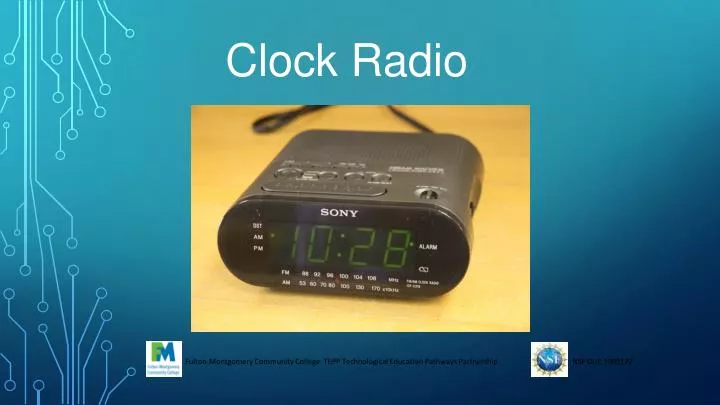
Fulton-Montgomery Community College TEPP Technological Education Pathways Partnership NSF DUE 1003122 Clock Radio
Our goal is to explore the main components in this everyday item: A combination clock/radio. The first step is to open the item. These two pictures show the case in the same orientation; But with the circuit board flipped To show both sides. This side has the connections. This side has the components.
The main functions are clearly separated into areas: The power section, at the left, has the main power coming in through a transformer (partially visible in the lower left corner). The clock functions are performed mostly in one integrated circuit, along with the display driver. The radio section at the right has most of its features visible on the other side of the board.
The Power Section: 120 VRMS enters the transformer’s primary winding at the top, through the black and white wires. The four wires coming out at the bottom have two signals, as shown on the oscilloscope image. From the image one can read that each signal is 15 VPP, which is: VRMS = VPP / (2√2) = 15 VPP / (2X1.41) = 5.30 VRMS When we compare the primary to secondary, we see that this is a: 120 VRRMS : 5.30 VRMS, or 22:1 step-down transformer.
The Power Section: One of the secondary voltages feeds power to the clock portion and the other feeds the radio. Each goes through a rectifier and simple capacitor filter to create unregulated DC. Additionally, this clock has a feature to keep track of the time if there is a power outage. Even though the display does not show the time, the clock continues to run from power supplied by a small battery. This battery is accessible from the back of the clock; but plugs directly into the circuit board. [01]
The Clock Section: Some electric clocks use the 60 Hz frequency from the AC power source which is very accurate over time. But since this model can run on a battery, it must be able to generate its own time source. This is commonly done with a crystal, which is an electromechanical device. Quartz crystals are cut and have conductors bonded to them. If an electric signal is applied, the crystal structure moves and the crystal actually changes shape. When the signal is removed, the crystal springs back to its original shape and returns the electric signal. If the electric signal is turned on and off at the correct rate (frequency), the crystal can oscillate at its “natural frequency” or “resonant frequency.” Just imagine how a spring and weight being pushed and released at the right rate will move a great distance.
The Clock Section: Some electric clocks use the 60 Hz frequency from the AC power source, which is very accurate over time. But since this model can run on a battery, it must be able to generate its own time source. This oscilloscope image shows the signal on one side of the crystal. The scope estimates this to be at 32.7677 kHz, which we can round to 32.768 kHz. The signal is fed into a digital circuit on the clock chip that divides it by a nice “round” binary number. You might recognize that: 32,768 = 215 It is easy to create a 15-bit binary counter that keeps counting and rolling over. The most significant bit will then produce a nice, clean pulse each second. This is used in the clock’s circuitry to count seconds, minutes, and hours, whether it is powered by AC or the backup battery.
The Clock’s Display Section: The image at the left shows some buttons that are pressed with small rods from the clock’s case to set the time and alarm. It also shows the ribbon cable that connects the printed circuit board to the display. The image at the right shows the other side of the board, with the clock chip. You can see how about half the pins go to the display connector.
The Radio Section: There are many ways to make a radio receiver. So let’s start with the most general radio concepts and think of the functions that must be performed to receive and use radio signals. Radio signals are made up of a high frequency “carrier” wave that can travel as electromagnetic radiation (not quite as high a frequency as light). This carrier wave is modified, or modulated, but the information signal (such as the sounds we want to transmit via radio). So radio receivers perform the following functions:
The Radio Section: The functions described on the previous slide have been performed in many different ways, which explains the vast variety of radios that have been made through the years. This radio uses “digital signal processing” to create a “software defined radio.” The function block diagram for a commonly-used Silicon Labs Si4735-D60 represents what happens inside the radio “chip.” → Antennas are connected through LNAs (low noise amplifiers) with AGC (automatic gain control). → The amplified antenna signals pass through ADCs (analog to digital converters) to the heart of this radio, the DSP (digital signal processor). → The DSP uses math to select one carrier frequency (radio station), and isolate the information, or original sound signal. → This passes through a DAC (digital to analog converter) to change it to an electric signal suitable for amplifying with components on the circuit board. [02]
The Radio Section: Although our clock radio’s “radio integrated circuit” might not be the exact same chip as described on the previous page, the components are similar. This radio chip uses an external tuner to select the radio station, whereas the chip on the previous page uses a “control interface” to connect to control buttons and a display.
Summary: • We have just looked at a common household item and found the following examples of topics taught in fundamental electrical courses: • Transformers, Primary / secondary ratios. • VRMS, VPP relationships. • Crystal oscillators. • Binary divide-by counters. • Radio receiver functions. • Digital signal processing radio receivers.
References: A Sony “Dream Machine “model ICF–C218 was used in this lab’s examples: [01] Datasheet included with the clock radio. [02] Datasheet for Silicon Labs radio receiver “on a chip” Si4730/31/34/35-D60. Revised: 04/27/14.