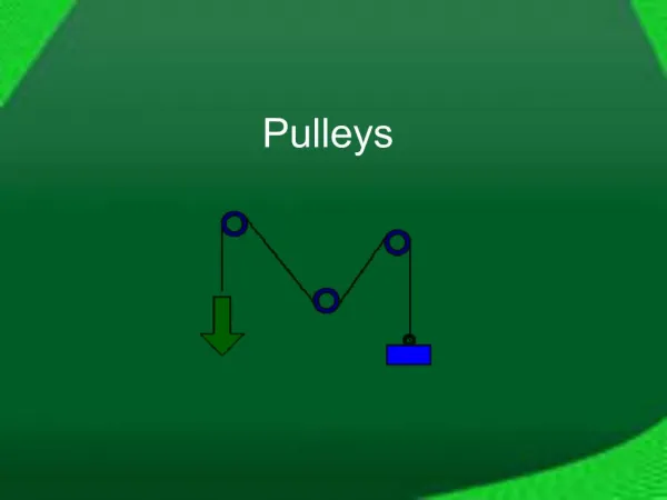
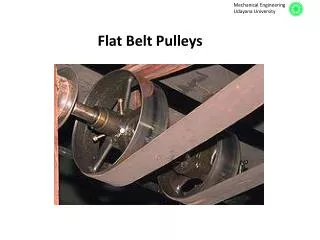
Flat Belt Pulleys
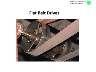
Flat Belt Pulleys. 2 Types of Pulleys for Flat Belts Following are the various types of pulleys for flat belts : 1. Cast iron pulleys, 2. Steel pulleys, 3. Wooden pulleys, 4. Paper pulleys, and 5. Fast and loose pulleys. 3 Cast Iron Pulleys

Flat Belt Pulleys
E N D
Presentation Transcript
2 Types of Pulleys for Flat Belts Following are the various types of pulleys for flat belts : 1. Cast iron pulleys, 2. Steel pulleys, 3. Wooden pulleys, 4. Paper pulleys, and 5. Fast and loose pulleys. 3 Cast Iron Pulleys The pulleys are generally made of cast iron, because of their low cost. The rim is held in place by web from the central boss or by arms or spokes. The arms may be straight or curved as shown in Fig. 1 (a) and (b) and the cross-section is usually elliptical. Fig. 2. Split cast iron pulley. Fig. 1. Solid cast iron pulleys.
The cast iron pulleys are generally made with rounded rims. This slight convexity is known as crowning. The crowning tends to keep the belt in centre on a pulley rim while in motion. The crowning may be 9 mm for 300 mm width of pulley face. 4 Steel Pulleys Steel pulleys are made from pressed steel sheets and have great strength and durability. These pulleys are lighter in weight (about 40 to 60% less) than cast iron pulleys of the same capacity and are designed to run at high speeds. Table 1. Standard number of spokes and their sizes according to IS : 1691 – 1980 (Reaffirmed 1990).
Other proportions for the steel pulleys are : The length of hub should not be less than 100 mm for 19 mm diameter spokes and 138 mm for 22 mm diameter of spokes. Thickness of rim = 5 mm for all sizes. A single row of spokes is used for pulleys having width up to 300 mm and double row of spokes for widths above 300 mm. 5 Wooden Pulleys Wooden pulleys are lighter and possesses higher coefficient of friction than cast iron or steel pulleys. These pulleys have 2/3rd of the weight of cast iron pulleys of similar size.
6 Paper Pulleys Paper pulleys are made from compressed paper fibre and are formed with a metal in the centre. These pulleys are usually used for belt transmission from electric motors, when the centre to centre shaft distance is small. 7 Fast and Loose Pulleys A fast and loose pulley (Fig. 3) used on shafts enables machine to be started or stopped at will. A fast pulley is keyed to the machine shaft while the loose pulley runs freely. The belt runs over the fast pulley to transmit power by the machine and it is shifted to the loose pulley when the machine is not required to transmit power. Fig. 3. Fast and loose pulley.
8 Design of Cast Iron Pulleys The following procedure may be adopted for the design of cast iron pulleys. 1. Dimensions of pulley The diameter of the pulley (D) may be obtained either from velocity ratio consideration or centrifugal stress consideration. The centrifugal stress induced in the rim of the pulley, σt = ρ.ν2 where ρ = Density of the rim material = 7200 kg/m3 for cast iron ν = Velocity of the rim = πDN / 60, D being the diameter of pulley and N is speed of the pulley. The following are the diameter of pulleys in mm for flat and V-belts. 20, 22, 25, 28, 32, 36, 40, 45, 50, 56, 63, 71, 80, 90, 100, 112, 125, 140, 160, 180, 200, 224, 250, 280, 315, 355, 400, 450, 500, 560, 630, 710, 800, 900, 1000, 1120, 1250, 1400, 1600, 1800, 2000, 2240, 2500, 2800, 3150, 3550, 4000, 5000, 5400. The first six sizes (20 to 36 mm) are used for V-belts only.
If the width of the belt is known, then width of the pulley or face of the pulley (B) is taken 25% greater than the width of belt. ∴ B = 1.25 b ; where b = Width of belt. According to Indian Standards, IS : 2122 (Part I) – 1973 (Reaffirmed 1990), the width of pulley is fixed as given in the following table : The following are the width of flat cast iron and mild steel pulleys in mm : 16, 20, 25, 32, 40, 50, 63, 71, 80, 90, 100, 112, 125, 140, 160, 180, 200, 224, 250, 315, 355, 400, 450, 560, 630. Table 2. Standard width of pulley.
The thickness of the pulley rim (t) varies from 300/D + 2 mm to 200/D + 3 mm for single belt and 200 D + 6 mm for double belt. The diameter of the pulley (D) is in mm. 2. Dimensions of arms The number of arms may be taken as 4 for pulley diameter from 200 mm to 600 mm and 6 for diameter from 600 mm to 1500 mm. Note : The pulleys less than 200 mm diameter are made with solid disc instead of arms. The thickness of the solid web is taken equal to the thickness of rim measured at the centre of the pulley face. The cross-section of the arms is usually elliptical with major axis (a1) equal to twice the minor axis (b1). The cross-section of the arm is obtained by considering the arm as cantilever i.e. fixed at the hub end and carrying a concentrated load at the rim end. The length of the cantilever is taken equal to the radius of the pulley.
The power is transmitted from the hub to the rim or vice versa, through only half the total number of arms. Let T = Torque transmitted, R = Radius of pulley, and n = Number of arms, ∴ Tangential load per arm, Maximum bending moment on the arm at the hub end, and section modulus, Now using the relation, σb or σt = M/ Z, the cross-section of the arms is obtained. Fig. 4. Cast iron pulley with two rows of arms.
The arms are tapered from hub to rim. The taper is usually 1/48 to 1/32. When the width of the pulley exceeds the diameter of the pulley, then two rows of arms are provided, as shown in Fig. 4. This is done to avoid heavy arms in one row. 3. Dimensions of hub The diameter of the hub ( d1 ) in terms of shaft diameter ( d ) may be fixed by the following relation : d1 = 1.5 d + 25 mm The diameter of the hub should not be greater than 2 d. The length of the hub, L = π/2 × d The minimum length of the hub is 2/3 B but it should not be more than width of the pulley (B).