Download
1 / 16
160 likes | 417 Views
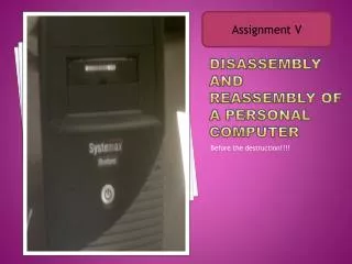
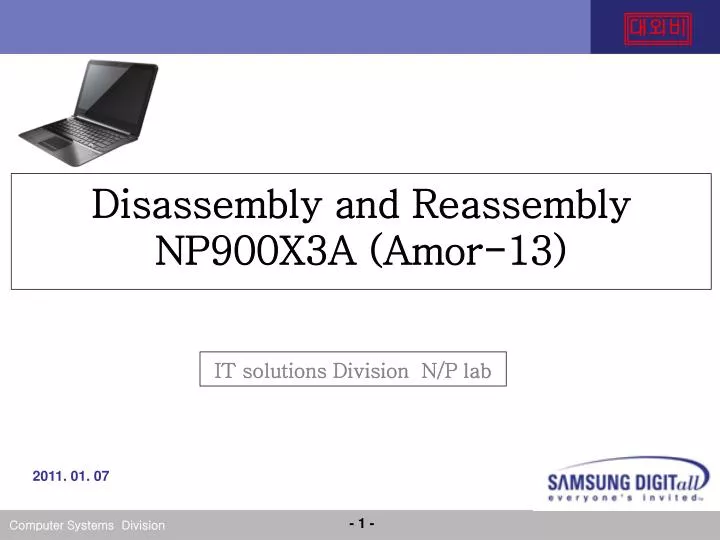
Disassembly and Reassembly NP900X3A ( Amor-13 ). IT solutions Division N/P lab. 2011. 01. 07. 1. Main System. Make sure to separate the AC adapter before disassembling the system. 2. Remove Bottom Rubber / Screw Remove Rubber Remove M2*L6 Screw Torque : 2.3~2.7kgfcm

E N D
Disassembly and Reassembly NP900X3A (Amor-13) IT solutions Division N/P lab 2011. 01. 07
1. Main System • Make sure to separate the AC adapter before disassembling the system. • 2. Remove Bottom Rubber / Screw • Remove Rubber • Remove M2*L6 ScrewTorque : 2.3~2.7kgfcm • Remove M2*L4 Screw Torque : 2.3~2.7kgfcm
1. Main System 3. Lift up Upper Bottom and separate. 4. Picture of system which removed Bottom.
1. Main System 5. Battery disassembling - Remove M2xL4: 2 EA (Red) Screw - Disassemble Battery Connector (Red)
1. Main System 6. Audio/USB2.0/Micro SD Card Door Port disassembling - Remove Audio Sub B/D FPC from 30pin connector(RED) - Remove Audio/USB2.0/Micro SD Card Door Port (RED)
1. Main System 7.SSD FPC &SSD disassembling - Remove Audio Sub B/D FPC from 30pin connector(RED) : Remove M2xL4: 2 EA (Red) Screw : Remove mSATA SSD(BLUE) : Remove uSATA SSD(RED)
1. Main System 8. SSD/HDD Bracket disassembling - Remove M2xL4: 3 EA (RED) Screw - Remove Antenna Cable from Cable hook(BLUE) 9. Main-to-Sub FPC disassembling - Remove Main-to-Sub FPC from 60pin connector (RED)
1. Main System 10. Touch PAD FFC disassembling - open the 6pin connector Latch(RED)and remove the touchpad FFC 11. Audio Cable disassembling - Remove audio Cable (L/R) from 2pin connector (L/R)
1. Main System 12. WirelessLAN Module disassembling - Remove Antenna cable from WLAN module antenna connector (RED) - Remove M2xL4 :1 EA Screw - Remove WLAN Module 13. Subboard disassembling - Remove M2xL4 1EA Screw(RED) - Remove Speaker cable from 2pin connector(BLUE) - Pick up the Subboard
1. Main System 14. FAN disassembling - Remove M2xL4 :2 EA Screw(RED) - Remvoe FAN cable from 4pin connector(BLUE) ` • 15. LCD Cable disassembling • Remove LCD cable from 30pin connector(RED)
1. Main System 16. DC in Cable disassembling - Remove DC in cable from 6pin connector(RED) • 17. Memory disassembling • Push the side switch of SODIMM (RED) and remove the memory
1. Main System • 18. USB3.0/Micro-HDMI/LAN Port disassembling • Remove M2xL4: 1 EA(BLUE) screw • - Remove LAN FPC from 50pin connector(RED) - Remove USB3.0/Micro-HDMI/LAN Door Port
1. Main System 19. Audio Cable disassembling - Remove L-Speaker cable from 2pin connector(RED) - Remove L-Speaker cable from 2pin connector(BLUE)
1. Main System 20. Mainboard disassembling - Remove M2xL4 : 5EA (RED) - Open the 30pin connector Latch(RED)and RemoveKBD FPC - Open the 6pin connector Latch(BLUE)and KBD Backlit FPC - Pickup the Mainboard
1. Main System 21. Heatsink disassembling - Remove frontScrew 4EA (RED) - Reverse the Mainboard • Remove backScrew 4EA (BLUE) • Remove Heatsink
1. Main System 22. Top Assy& LCD Assy disassembling - Remove HingeScrew 2ea * 2