Download
1 / 51
570 likes | 843 Views
Understand gage types, calibration, and measurement acquisition for steel beams and test panels. Gain insights on SSPC-PA2 procedures and verification methods for coating thickness. Enhance your knowledge in measurement accuracy.

E N D
Complying with SSPC-PA2, “Measurement of Dry Coating Thickness with Magnetic Gages” William D. Corbett KTA-Tator, Inc.
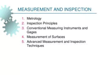
Complying with SSPC-PA 2 • Webinar Content • Overview and Purpose of SSPC-PA 2 • Definitions • Proper Gage Use • Acquisition of Measurements • Frequency of Measurements • Tolerance of Measurements • Measuring Coating Thickness on Steel Beams (girders) • Measuring Coating Thickness on Test Panels • Potential Changes to SSPC-PA 2 (2011/2012)
Learning Objectives/Outcomes • Completion of this webinar will enable the participant to: • Describe the purpose of SSPC-PA 2 • Describe the differences between Type 1 and Type 2 gages • Describe the processes associated with calibration, verification of accuracy and adjustment • Explain Base Metal Reading acquisition • Describe the differences between measurement acquisition using manual verses electronic gages • Describe the frequency and tolerance of measurements • Describe the measurement acquisition process for steel beams. laydowns and test panels
Overview and Purpose of SSPC-PA 2 • Describes the procedures to measure the thickness of dry, nonmagnetic coatings applied to magnetic substrates • Measurements are acquired using commercially available gages (two “types”) • Procedures for gage adjustment & measurement acquisition are described • Procedure for determining conformance to specified thickness range over extended areas is described
Definitions • Gage Reading • Spot Measurement • Calibration • Verification of Accuracy • Gage Adjustment • Coating Thickness Standard (Test Block) • Shim (Foil) • Dry Film Thickness Reference Standard • Accuracy • Structure
Gage Descriptions • Gage type is determined by magnetic properties employed to measure thickness (not the read-out mode) • Type 1 – Pull-off Gages • Type 2 – Electronic Gages • Gages not addressed by SSPC-PA 2 • Measurement of coatings on non-ferrous metal surfaces • Measurement of coatings on non-ferrous surfaces • To qualify for use, gages must have an accuracy of +/- 5% or better (0.1 mil or better when < 1 mil DFT)
Gage Types Type 1 – Pull-off Gages Type 2 – Electronic Gages
Gage Types, continued • Type 1 – Pull-off Gages • Permanent magnet contacts coated surface • Force required to detach magnet is measured • Force interpreted as the coating thickness on scale or display • Scale is nonlinear
Gage Types, continued • Type 2 – Electronic Gages • Electronic circuitry converts reference signal to coating thickness
Gage Calibration • Performed by the gage manufacturer or qualified laboratory • Certificate of calibration traceable to a National Metrology Institute required • No standard calibration interval (established based on experience & work environment) • One year interval is common
Verification of Type 1 Gage Accuracy • Performed using reference standards (traceable test blocks) • Beginning and end of each work shift • If gage is dropped or readings are suspect • Record: • Serial no. of gage & standard • Stated & measured thickness • Use of shims (foils) not permitted
Verification of Type 1 Gage Accuracy • Single Point Verification • Select one reference test block representing the mid-range of the anticipated coating thickness • E.g., 4-6 mils (100-150 µm), select 5 mil (125 µm) reference standard • Tw0 Point Verification • Select a reference test block below and above the median anticipated coating thickness • E.g., 5 mils (125 µm), select 3 mil (75 µm) and 7 mil (175 µm) reference standards
Verification of Type 1 Gage Accuracy • Most Type 1 gages cannot be “adjusted” • Adjustments to the helical spring may void the gage warranty • Combined tolerance of gage and reference standard determines gage accuracy • E.g., if gage accuracy is 5% and reference standard accuracy is 3%, combined tolerance is ~6%, calculated as: √ 52 + 32 • On a 10 mil reference standard, the gage reading can range from 9.4-10.6 mils
Correction for Surface Roughness • Base Metal Reading (BMR) • Effect of surface roughness on coating thickness gage • NOT surface profile • Measure the prepared, uncoated substrate; calculate average BMR • Deduct BMR from measured coating thickness BMR
Correction for Surface Roughness Measuring Base Metal Effect with Type 1 DFT Gage Average BMR: 21 µm (0.8 mil)
BMR Correction for Multiple Coat Systems Measured Primer Thickness: 102 µm (4.0 mils) BMR: 13 µm (0.5 mils) Actual Primer Thickness: 89 µm s (3.5 mils) Measured Primer + Finish Thickness: 178 µm (7.0 mils) BMR: 13 µm (0.5 mils) Actual Total System Thickness: 165 µm (6.5 mils)
Correction for Surface Roughness • What if access to blast cleaned steel is not available (already coated)? • Appendix A2.3 addresses smooth surface adjustment • Verify gage accuracy on a smooth surface (per gage manufacturer instructions) • Deduct “assumed” approximate correction value from each gage reading (see Table A2)
Correction for Surface Roughness Table A2 Typical Gage Correction Values Using ISO 8503 Profile Grades
Adjustment of Type 2 Gages • Follow the gage manufacturers step-by-step procedures for gage adjustment • Instructions vary by gage manufacturer • Adjustment is typically performed using plastic shims (foils) of known thickness
Verification of Type 2 Gage Accuracy • Verify accuracy per manufacturer instructions • Typically performed using reference standards or shims • Beginning and end of each work shift • If gage is dropped or readings are suspect • Record: • Serial no. of gage & standard • Stated & measured thickness
Verification of Type 2 Gage Accuracy • Single Point Verification • Same as described for Type 1 gages • Can use reference blocks or shims (per gage manufacturer) • Tw0 Point Verification • Same as described for Type 1 gages • Can use reference blocks or shims (per gage manufacturer)
Verification of Type 2 Gage Accuracy • If smooth reference standards are used (A), user must correct* for surface roughness • If shims (foils) are used (over the prepared steel; B), no correction is needed *Via Base Metal Reading (BMR) A B
Adjustment of Type 2 Gages • Aligning a gage’s thickness readings to those of a known thickness value to improve gage accuracy on a specific surface or within a measuring range • Corrects for: • Substrate properties • Coating • Ambient conditions and surface temperature
Acquiring Coating Thickness Measurements – Type 1 Gages • Rotate the thumbwheel forward to set the magnet (or depress the power button on the digital model) • Retract the thumbwheel until the magnet breaks contact (digital version breaks contact automatically) • Read coating thickness from the gage dial or display
Acquiring Coating Thickness Measurements – Type 2 Gages • Power-up the gage • Position the probe on the coated surface until a measurement is displayed • Most models have integral and remote probes
Type 2 Gage Data Management • Many Type 2 gages have “PA 2” Data Management Systems • Programmed to collect correct no. of values, perform averaging and indicate conformance • Features and programs vary by gage manufacturer
Measurement Frequency • Terminology: • Gage Reading: A single reading at one location • Spot Measurement: The average of at least 3 gage readings made within a 1.5” (4 cm) diameter circle • Area Measurement: The average of 5 spot measurements made within a 100 square foot (10 square meter) area
Measurement Frequency • If the structure is less than 300 square feet, (~28 square meters) each 100 square feet (~10 square meters) is measured • If the structure is between 300 and 1000 square feet (~28 and 100 square meters), arbitrarily select 3 random 100 square foot (~10 square meter) test areas and measure
Measurement Frequency • For structures exceeding 1000 square feet (~100 square meters), arbitrarily select 3 random 100 square feet (~10 square meter) testing areas for the first 1000 square feet (~100 square meters), and 1 random 100 square foot(~10 square meter) testing area for each additional 1000 square feet (100 square meters)
Measurement Frequency Example 1 (US Standard) Structure Size: 900 square feet No. of Areas: 3 areas No. of Spots: 3 Areas x 5 Spots/Area = 15 Spots Minimum No. of Gage Readings: 15 Spots x 3 Readings/Spot = 45 Gage Readings
Measurement Frequency Example 2 (US Standard) Structure Size: 55,000 square feet No. of Areas: 3 + 54 = 57 areas No. of Spots: 57 Areas x 5 Spots/Area = 285 Spots Minimum No. of Gage Readings: 285 Spots x 3 Readings/Spot = 855 Gage Readings
Measurement Frequency Example 3 (metric) Structure Size: 5200 Square Meters No. of Areas: 3 + 51 = 54 areas No. of Spots: 54 Areas x 5 Spots/Area = 270 Spots Minimum No. of Gage Readings: 270 Spots x 3 Readings/Spot = 810 Gage Readings
Measurement Tolerance • Individual gage readings obtained and averaged to generate a spot measurement are unrestricted (unusually low or high readings that can’t be repeated are discarded) • Spot measurements (the average of the gage readings) must be within 80% of the minimum thickness and 120% of the maximum thickness • Area measurements must be within specified range
Measurement Tolerance EXAMPLE: • Target DFT: 4-6 mils (102-152 microns) • Individual gage readings unrestricted • Spot measurements must be between 3.2 mils and 7.2 mils (82 microns and 182 microns) • Area measurement must be between 4 and 6 mils (102 and 152 microns) • If spot or area measurements are out of tolerance, measure each 100 sq. ft (~ 10 sq. meter) area coated during that work shift to isolate the nonconforming area (independent of structure size)
Specifying Coating Thickness • Specifications should indicate the range of coating thickness (e.g., 5-7 mils or 127-178 microns), not as a single value (e.g., 5 mils or 127 microns) • Nearly impossible for an applicator to achieve a single thickness value • The Quality Control and Quality Assurance inspectors should not have to assume a range
Cumulative Thickness Measurements • Nondestructive coating thickness gages: • Most cannot distinguish coating layers • Measure the total cumulative thickness
Cumulative Thickness Measurements EXAMPLE: Specification Primer thickness: 3-5 mils (76-127 microns) Intermediate Coat Thickness: 4-6 mils (102-152 microns) Finish Coat Thickness: 2-3 mils (51-76 microns) Target After: Primer Application: 3-5 mils (76-127 microns) Intermediate Application: 7-11 mils (178-279 microns) Finish Coat Application: 9-14 mils (229-356 microns)
Appendix 3: Measuring Coating Thickness on Steel Beams (Girders) • Full Determination • Sample Determination • Beams < 20 ft (6 m) • Beams 20 ft - 60 ft (6 m-18 m) • Spot measurement tolerance (80% of minimum and 120% of maximum) applies • The average of all spot measurements (per area) must conform to specified range • Measurement locations on stiffeners arbitrarily selected Stiffener
Appendix 3: Measuring Coating Thickness on Steel Beams (Girders) • Full Determination • Divide beam into 5 equal sections along the length • Web > 36”: Obtain one spot measurement in 14 areas, per section (total of 70 spot measurements) • Web < 36”: Obtain one spot measurement in 12 areas, per section (total of 60 spot measurements)
Full Determination Note: Areas 2, 6, 8 and 12 (Toe) may not be measured
Appendix 3: Measuring Coating Thickness on Steel Beams (Girders) • Sample Determination • Beam length < 20 ft: Obtain 2 spot measurements randomly distributed in all 12 areas (total of 24 spot measurements) • Beam length 20-60 ft: Obtain 3 spot measurements randomly distributed in all 12 areas (total of 36 spot measurements) Note: If toe areas are not included, measure in 8 areas (16 or 24 spot measurements)
Appendix 4: Measuring Coating Thickness on Laydowns • Laydown: Group of steel members laid down to be painted in one shift by one applicator • Full DFT Determination • Beams (girders) • Miscellaneous parts • Sample DFT Determination • Beams < 20 ft (6 m) • Beams 20 ft - 60 ft (6 m-18 m)
Appendix 4: Measuring Coating Thickness on Laydowns • Full DFT Determination • Beams: Same procedure described earlier • Miscellaneous parts: 1 spot measurement per “surface” (minimum of 5 spots) • Spot measurement tolerance (80% of minimum and 120% of maximum) applies • The average of all spot measurements (per area) must conform to specified range
Appendix 4: Measuring Coating Thickness on Laydowns • Sample DFT Determination • Beams: Same procedure described earlier • Miscellaneous parts: 3 spot measurements per part • Spot measurement tolerance (80% of minimum and 120% of maximum) applies • The average of all spot measurements (per area) must conform to specified range
Appendix 5: Measuring Coating Thickness on Test Panels • Minimum panel size: 3” x 6” (7.5 x 15 cm) • Maximum panel size: 12” x 12” (30 x 30 cm) • Use Type 2 gage • Two gage readings from top, middle and bottom third • At least 0.5” from edge and 1” from other readings • 80% min.120% max. applies to gage readings
Appendix 6: Measuring Thickness of Thin Coatings on Abrasive Blast Cleaned Test Panels • “Thin” is considered 1 mil (25.4 µm) or less • Obtain 10 gage readings from each of three “zones” • Calculate the mean and standard deviation in each zone • The mean of all three zones is the coating thickness 10 gage readings 10 gage readings 10 gage readings
Potential Changes to SSPC PA 2 • Most recent revision is May 2004 (editorial changes to Appendix 6 made in 2009) • Document revisions and updating in progress • Changes may include: • Re-title, “Procedure for Determining Conformance to Dry Coating Thickness Requirements” • Use in concert with ASTM D 7091* • Measurement of coatings on ferrous and non-ferrous metal surfaces • Information on calibration and verification of accuracy removed (already in ASTM D 7091) • *Primarily focus on frequency and tolerance of measurements (instead of gage use)
Summary • During this webinar, we have: • Described the purpose of SSPC-PA 2 • Described the differences between Type 1 and Type 2 gages • Described the processes associated with calibration, verification of accuracy and adjustment • Explained Base Metal Reading acquisition • Described the differences between measurement acquisition using manual verses electronic gages • Described the frequency and tolerance of measurements • Described the measurement acquisition process for steel beams, laydowns and test panels