Download
1 / 31
330 likes | 599 Views
Hydraulic Analysis of Jamma’in Water Distribution Network. Importance Of Water. Water is life. Living on the earth may be impossible without adequate water quality and quantity .

E N D
Importance Of Water • Water is life. Living on the earth may be impossible without adequate water quality and quantity. • Water makes up more than half of your body weight and a person can't survive for more than a few days without it. • Water is needed on daily basis in all activities
Importance Of WDNs • . Water Distribution Networks (WDNs) are required for suppling users with water • WDNs connect consumers to sources of water by using hydraulic components, such as pipes, valves, reservoirs and pumps
Importance Of WDNs • WDNs must transmit and distribute water for population. Using a network of pipes to distribute water is a suitable and a safe way since the pipes cover the water
Objectives of this project • The main goals of this project are: • To evaluate the existing WDNs system in Jamma’in town . • To recommend lane modifications to fit the increasing water demands up to planning horizon of 2035.
velocity and pressure • According to the Palestinian Water Authority, velocity and pressure limits are as follows: • The velocities here are in the range of (0.3-2) m\s. • The pressure limits are in the range of (20-90) m.
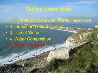
Water resource in Palestine • Groundwater • Groundwater basins in West Bank include: • 1. Eastern basin • 2. Western Basin • 3. North East basin
Water resource in Palestine • Surface water • Wadis • Jordan River • Mekerot
Descriptive of study area • Jamma’in is located about 16 km to the southwest of Nablus. with total surface area of about 21,000 dunums. • The built up areas of it is 2,912 dunms and its population is around 6,000 people
Jamma’in town is a hilly area, the hills being used for pasture, with elevations varying from 400 m to 600 m above sea level in the hills
The source of water in Jamma’in town is Mekrot company. It is to pump water to reservoir of capacity equals to 280 cubic meters and elevation is 612m above mean sea level. where water is to flow by gravity distribution system of the service area
Jamma’in Network • The total length of the pipes in the proposed network is estimated at about 19.5 Km with pipe diameters of 4", 3",2"and 1“ • As mentioned above, in the existing system water is directly pumped through the mains to the consumers, but in the proposed system, it is planned to gravity (without pump) the water through a pipeline to an existing reservoir
Steady-State Analysis • Steady state analysis indicates the steady condition of using the water all the day hours • Steady state analysis was performed on the year of (2009); this means the existing condition in the village. We use 2009 year data to for analysis.
The data needed for analysis • Demand for each node • Elevation for each node(obtained from contour map ) • Diameter and length for each pipe (obtained from AutoCAD drawing of Jamma’in WDN) • Elevation and Volume of the reservoir
Demand Calculation To estimate the demand we need the following data: • Water Consumption : this obtained from Municipal of Jamma’in • Area of each node : from AutoCAD • The area for each zone in AutoCAD drawing is equivalent to the area of the houses served by the nodes
Demand Calculation • Factor(Population density) : this factor equals to the population rate per square meter of homes and this factor equals 0.0118 person/ m² • Factor of losses Factor= (1/ (1- losses %)
Demand Calculation • Loss: is the difference between the quantity of water delivered to the system and the quantity registered by the water meters of the consumers . • Losses from the network take from the data that related to year 2009: • Percent of losses= (( Demand- Consumption)/ Demand)
Demand Calculation • DEMAND = 0.0188 * water Consumption * Area of the Zone (node)* losses factor The obtained value used in EPANET analysis
Future per Capita Water Demand • To estimate future water demand for each node, the nodal water demand shall be multiplied by the future demand factor • Future Multiplication Factor = (Future demand/Present demand) *(Future population/Present population)
Future demand = 125 liter/capita/day (it takes in the range100-150 l/c/d) • Future population Pf = Pp (1+r) ⁿ Pf: future population Pp: present population r: growth rate n: # of years
Hazen-William Coefficient • For Present analysis the Hazen-William Coefficient (CHW) =120 • For Future analysis the Hazen-William Coefficient (CHW) =100.
Design • It should be taken in consideration that the pipes diameters which used in establishing the network may affect over the pressure; therefore we need to choose the best diameters that make the WDN works in the best rate.
Design • It would be ideal if the future design for the WDN satisfies the acceptable range of pressure and velocity for each node, so that the network works in it is maximum efficiency and serviceability • The velocities here are in the range of (0.3-2) m\s. • The pressure limits are in the range of (20-90) m.