Download
1 / 36
360 likes | 401 Views
Explore system level design considerations for DC microgrids, including transient constraints, stability, and metamodeling for components. Learn about optimization techniques, passive components, and fitness functions.

E N D
S.D. Sudhoff, H. Suryanarayana*School of Electrical and Computer EngineeringPurdue University*ABBPECI 2016 Thoughts on System Level Design of DC Microgrids • This work was supported by the Office of Naval Research (ONR) through Grant N00014-08-1-0080 and N00014-14-1-0160 • Harish Suryanarayana was partially funded by a fellowship provided by ABB Inc.
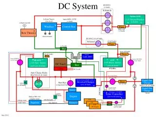
DC Microgrids Source: ESRDC - USC
Steady-State Power Flow • Multiple Generators (2 main, 2 aux) • Energy Storage (?) • Propulsion (2) • Radar (1) • Weapon Systems (?)
Transient Constraints • Transient specifications are based on MIL-STD-704F Start-up constraint Transient event constraint
Distortion Constraints • The rms voltage ripple at each bus is subject to a limit • The rms current ripple going into each component, when supplied by / supplying an ideal source / ideal load is subject to a limit
Consider a Trivial System Minimize metrics (mass, loss, …) subject to all constraints (transient, distortion, stability, …) being met
Reducing Dimensionality • Vendor • Power Electronics Building Block (PEBB) • Fixed switching frequency • Fixed gate drive, snubber • Shock, vibration, thermal • Control platform • System Integrator • Programmable controls • Exterior passives
Degrees of Freedom • Machine: 1 at 20 DOF • Inductors: 5 at 10 DOF • Capacitors: 4 at 4 DOF • Transformers: 1 at 15 DOF • Control gains: 10 DOF • Total: 109 DOF
Further Reducing Dimensionality • Target: Power Magnet Components • Approaches • Catalogs • Densities • Metamodels
Metamodeling • Consider an simple inductor …
Scaling • To scale • Dimensions, areas, volumes, mass: • Current, current density: • Power, energy, time: • Time, frequency: • Not scaled • Magnetic flux density • Voltage
Scaled Machine Design • To scale • Dimensions, areas, volumes, mass: • Force, torque: • Current, current density: • Power, energy, time: • Frequency, speed • Not scaled • Magnetic Flux density • Voltage • Base
Challenge: Core Loss • MSE Model • Modification • Observation
Challenge: Poles • Stator backiron volume decreases • Stator end conductor volume decreases • Rotor backiron volume decreases • Increase in loss with frequency compensated for by decrease in volume
Challenge: Poles • The limiting factor - leakage
Degrees of Freedom • Machine: 1 at 1 DOF • Inductors: 5 at 2 DOF • Capacitors: 4 at 4 DOF • Transformers: 1 at 1 DOF • Control gains: 10 DOF • Total: 18 DOF - Piece of Cake Rubarb Pie!
Back to Our Test System… Minimize metrics (mass, loss, …) subject to all constraints (transient, distortion, stability, …) being met
Design Space Control Parameters Passive Components
Fitness Function • The fitness function is constructed as follows:
Results of Optimization • The optimization routines were evaluated using an initial population of 2000 individuals for 80 generations.