Download
1 / 31
310 likes | 449 Views
Unit 10 Light. Discover PHYSICS for GCE ‘O’ Level Science. Thin Converging Lens. Unit 10.6 Converging Lens. Learning Outcomes In this section, you’ll be able to: Describe the action of a thin converging lens on a beam of light Define the term focal length for a converging lens.

E N D
Unit 10 Light Discover PHYSICS for GCE ‘O’ Level Science Thin Converging Lens
Unit 10.6 Converging Lens Learning Outcomes In this section, you’ll be able to: • Describe the action of a thin converging lens on a beam of light • Define the term focal length for a converging lens
Unit 10.6 Converging Lens What is a lens? A lens is a piece of clear plastic or glass with curved surfaces. Lenses are widely used in spectacles, cameras, projectors and many other optical instruments.
Unit 10.6 Converging Lens How does a lens refract light? A lens can be thought of as a set of blocks and prisms (see Fig 10.53 and 10.54). Fig 10.53 Converging Lens Fig 10.54 Diverging Lens
Unit 10.6 Converging Lens How does a lens refract light? Parallel light rays will incident different parts of the lens at different incident angles. Light rays refract the most at the outermost part of the lens, while less or no refraction occurs in the middle portion. Fig 10.53 Converging Lens Fig 10.54 Diverging Lens
Unit 10.6 Converging Lens How does a lens refract light? As a result, the light rays will converge (Fig 10.53) or diverge (Fig 10.54) behind the lens. Fig 10.53 Converging Lens Fig 10.54 Diverging Lens
Unit 10.6 Converging Lens Types of Lenses – Converging and Diverging • For converging lenses, parallel light rays are brought to focus at a point. • For diverging lenses, parallel light rays tend to be spread out. Insert table 12.4
Unit 10.6 Converging Lens Thin converging lens and its main features • Optical centre C • Principal axis • Focal point F – All parallel rays to the principal axis converge at the focal point F. • Focal length, f – The distance between the optical centre C and the focal point F. • Focal plane Fig 10.58 Converging lens Fig 10.59 Converging lens
Unit 10.6 Converging Lens Tracing path of light through a thin converging lens Insert fig for path 1,2 and 3 on pg 247
Unit 10.6 Converging Lens Key Ideas • Lenses are used to converge and diverge a beam of light. • The main features of a thin converging lens are: • Optical centre C • Focal point F • Focal length f • Principal axis
Unit 10.6 Converging Lens Key Ideas • Three definite paths for light rays passing through a thin converging lens: Insert Fig for path 1, 2 and 3 on pg 247
Unit 10.6 Converging Lens Test Yourself 10.6 • Fig 10.61 shows light rays passing through a converging lens. Is the ray diagram correct? Give your reasons. Answer: For a converging lens, light rays should be refracted in such a way that they tend to converge. So the correct ray path is:
Unit 10.7 Ray Diagram for Lenses Learning Outcome In this section, you’ll be able to: • Draw ray diagrams to illustrate the formation of real and virtual images of an object formed by a thin converging lens.
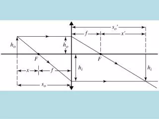
Unit 10.7 Ray Diagram for Lenses How to locate the position of an image? 3 steps to locate the image: Step 1: Set up the lens and the ray diagram. Step 2: Placing the object. Step 3: Trace the light rays using paths 1, 2 or 3 as learned on pg 189.
Unit 10.7 Ray Diagram for Lenses How to locate the position of an image? Step 1: Set up the lens and the ray diagram • Draw principal axis • Draw the lens • Mark optical centre C • Mark the focal point F Fig 10.62 Step 1
Unit 10.7 Ray Diagram for Lenses How to locate the position of an image? Step 2: Placing the object. • Place the object O to the left of the lens. • Mark the object distance as u. Fig 10.63 Placing the object
Unit 10.7 Ray Diagram for Lenses How to locate the position of an image? Step 3: Trace the light rays and draw the image. • Draw 2 of the 3 definite paths e.g. Path 1 and 2. • The point where the two light paths intersect is the position of the image. Fig 10.64 Draw paths and locate image
Unit 10.7 Ray Diagram for Lenses How to locate the position of an image? In this example, the image is said to be a real image. A real image is formed when the light rays converge at the point of the image. If a screen is place at this position, the image will be captured clearly on screen. Fig 10.64 Formation of a real image
Unit 10.7 Ray Diagram for Lenses Virtual image formed by a converging lens When the object O is placed near to the lens such that the object distance u is less that the focal length f, then a virtual image is formed. A virtual image cannot be captured on screen. Fig 10.65 Virtual image is formed when u < f
Unit 10.7 Ray Diagram for Lenses Table 10.5 Types of images formed by a converging lens with different values of object distances u.
Unit 10.7 Applications of Converging Lenses Converging Lenses can be used in various optical instruments: • Magnifying glass • LCD projector • Camera • Visual correction for long-sightedness
Unit 10.7 Applications of Converging Lenses Magnifying glass – See Worked Example 10.11 When the object is placed such that u < f, image is magnified, virtual and upright. Fig 10.67 Magnifying glass
Unit 10.7 Applications of Converging Lenses LCD Projector – In the LCD projector the object is placed between f and 2f such that the image formed is magnified, real and inverted. Fig 10.68 LCD Projector
Unit 10.7 Applications of Converging Lenses Camera Lens – For the camera lens, the image is diminished, real and inverted. Fig 10.69 Camera Lens
Unit 10.7 Applications of Converging Lenses Visual Correction for Long-sightedness People with long-sightedness are unable to focus a clear image of near objects on the retina. Fig 10.70(a) Long-sightedness
Unit 10.7 Applications of Converging Lenses Visual Correction for Long Sightedness Spectacles with converging lenses can partially converge the light rays, thereby helping to form a sharp image on the retina. Fig 10.70(b) Converging lens helps a long sighted eye to focus a clear image on the retina
Unit 10.7 Ray Diagrams for Lenses Key Ideas • Ray diagrams can be constructed to locate the position and type of image formed by a thin converging lens. • Light paths using Path 1 and Path 2 to construct the ray diagram. • A real and inverted image is formed when object distance u > focal length f. The image is formed on the other side of the lens.
Unit 10.7 Ray Diagrams for Lenses Key Ideas 4. A virtual and upright image is formed when the object distance u < focal length f. The image is formed on the same side of the lens as the object. • Converging lenses can be found in a wide variety of optical instruments such as the camera and projector.
Unit 10.7 Ray Diagrams for Lenses Test Yourself 10.7 • How far from a thin converging lens must an object be placed to produce a magnified image? Answer: When object distance u < focal length f, the image is magnified, virtual and upright. (See Worked Example 10.11). Eg. Magnifying Glass When object distance u is between f and 2f, the image is magnified, real and inverted. (See Worked Example 10.12). Eg. Projector.
Unit 10.7 Ray Diagrams for Lenses Test Yourself 10.7 • State two applications of converging lenses. Answer: Any two of the following: • Use as magnifying glass • In LCD projector • Camera lenses • Use for visual correction for long sightedness