Download
1 / 8
80 likes | 286 Views
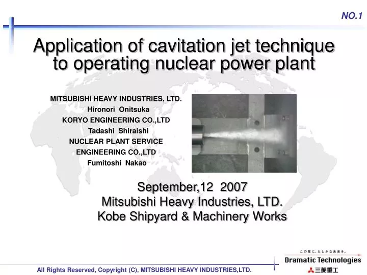
Application of cavitation jet technique to operating nuclear power plant. MITSUBISHI HEAVY INDUSTRIES, LTD. Hironori Onitsuka KORYO ENGINEERING CO.,LTD Tadashi Shiraishi NUCLEAR PLANT SERVICE ENGINEERING CO.,LTD Fumitoshi Nakao. September,12 2007

E N D
Application of cavitation jet technique to operating nuclear power plant MITSUBISHI HEAVY INDUSTRIES, LTD. Hironori Onitsuka KORYO ENGINEERING CO.,LTD Tadashi Shiraishi NUCLEAR PLANT SERVICE ENGINEERING CO.,LTD Fumitoshi Nakao September,12 2007 Mitsubishi Heavy Industries, LTD.Kobe Shipyard & Machinery Works
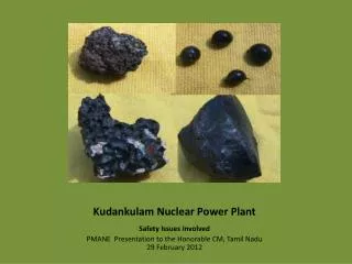
Application of the cavitation jet technique to the operating plant(1/7) 1. Introduction Decontamination is implemented during periodical inspection so that radiation exposure from radioactive clad accumulated on systems is reduced for workers engaged in operations, such as inspection and maintenance. For decontamination, to the extent possible cost- effective method is required. MHI promotes and implements cleanup and decontamination by means of pressure impact generated by the cavitation jet to meet these requirements with agreement of customers. This presentation introduces application of the cavitation jet technique to the operating nuclear power plant .
Application of the cavitation jet technique to the operating plant(2/7) 2. Principle of cavitation jet generation Cleanup and decontamination with cavitaion jet (CJ) are technologies to generate cavitations by jetting high pressure water through the dedicated nozzle into the water for the purpose of striping off radioactive clad from the surface of subject equipment . Impact wave Contraction Bubble Liquid
Application of the cavitation jet technique to the operating plant(3/7) • 3. Features • ① Highly effective physical impact allows effective • removal of fouling such as clad, etc. comparing to • aerial high pressure water cleanup. • ② Since the cleanup is implemented in the water, it • precludes propagation of possible contamination • such as dusts generated in the air. Water • shielding can limit radiation exposure during • decontamination activity. • ③ Highly effective physical impact can be achieved • by compact facility. • ④ No effect on the surface of the equipment may • occur due to short period of time required for • decontamination and cleanup.
SFP Pure water for CJ High pressure pump A/B C/V Lifting frame and basket Fuel transfer tube Cleanup device Rail Temporary platform Channel drain Image of channel decontamination activity Application of the cavitation jet technique to theoperating plant(4/7) 4. Application examples (1)Manual cleanup by operators For parts replacement operation inside the SFP (facilities inside the canal), removal of radioactive allows reduction of environmental dose rate. No decontamination → after decontamination:Approx.80 % reduction of radiation dose for parts replacement operation
Application of the cavitation jet technique to theoperating plant(5/7) 4. Application examples (2)Equipment decontamination in the dedicated cleanup tank To accomplish reduction of radiation exposure during works for periodical inspection, the dedicated cleanup system decontaminates subject parts by means of cavitation jet. This achieves uniform decontamination effect regardless of its irregularity of the surface based on effective range of generated cavitation. Full view of decontamination tank
High pressure pump for CJ (the existing pump can be utilized) 22MPa,15L/min P Nozzle transfer system F Water recovery line Control panel Decontamination vessel Strainer Abrasive particles suction nozzle CJ+Jet flow Abrasive particles SG insert plate Rotation table Decontamination unit platform (existing unit can be utilized) Application of the cavitation jet technique to theoperating plant(6/7) 2.Application example (3) High efficiency decontamination with abrasive particles To reduce radiation exposure during maintenance of SG insert plate, surface dose rate is reduced by adding abrasive particles to cavitation jet for removing highly adhesive radioactive clad. ○Maintenance activity without decontamination → Maintenance activity after decontamination :Approx. 60% reduction (including radiation exposure during decontamination work) System schematic Heat transfer tubes (4) Application for other purpose than radiation exposure reduction (Sludge removal from SG tube sheet area) Application of the cavitation jet technique to remove accumulated sludge. This achieves uniform decontamination of the heat transfer tube surface and sheet surface including shadow zones. Approx.10mm Jet direction of CJ Verification test (Paint stripping test)
Application of the cavitation jet technique to theoperating plant(7/7) 5. Summary We MHI will further promote various advanced techniques including cavitation jet technique to flexibly meet needs of operating plants based on the principle of ALARA .