Why render terrains?
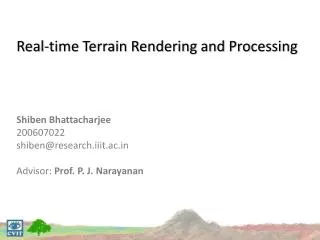
Real-time Terrain Rendering and Processing Shiben Bhattacharjee 200607022 shiben@research.iiit.ac.in Advisor: Prof. P. J. Narayanan. Why render terrains?. Terrains are a basic need in most graphics application Geographical information systems E.g. Google Earth Entertainment: Computer Games

Why render terrains?
E N D
Presentation Transcript
Real-time Terrain Rendering and ProcessingShibenBhattacharjee200607022shiben@research.iiit.ac.inAdvisor: Prof. P. J. Narayanan
Why render terrains? • Terrains are a basic need in most graphics application • Geographical information systems • E.g. Google Earth • Entertainment: • Computer Games • Animation Movies • Study of terrains
Chapters • What is terrain rendering? • Real-time Terrain Rendering • Spherical Terrain Rendering • Painterly Rendering of Terrains
Terrain Rendering • Do not render geometry which is not visible • View Frustum Culling • Control the detail of geometry rendered according to amount of visibility • Level of Detail scheme • Keep a representation (data structure) • Memory management • Fast processing • Accessibility
Theoretically… • Divide the terrain in tiles • Discard tiles not in view • Reduce the detail of tiles farther from camera
Representation Array of tilelets (Rendering by GPU) Array of tiles (Rendering by CPU) Blocks (Used for caching)
Global LoD System • Merge level • LoD based on elevation • Whole GPU cache resolution is changed • Lowered, if camera is going higher • Increased, if camera is coming to the ground • Distance level • Tiles’ detail is reduced based on camera distance
Terrain Rendering • Divided in two stages • Stage 1: CPU • View frustum culling (level1) • Render tiles
Terrain Rendering • Stage 2: GPU • Tessellate region between vertices • Access height data for elevation of vertices • 2nd Level of culling • Only for tiles intersecting with view frustum
2nd Level of Culling • Test tilelet bounds against screen bounds • If outside, GS doesn’t generate tilelet • CPU load reduced Distance based lod Culled tilelet Tilelets which undergo 2nd level of culling Tilelets assumed to be inside
Constant Memory Usage Camera moving up Wide view range required Detail is not necessary
Caching, types of job Merge 4 blocks into 1 Bring new block from main memory
Terrain Deformation • Blocks reside in memory as textures • Edited with fragment shader (like GPGPU) • Procedural deformation or mouse based interactions • Cache is edited directly, thus changes are reflected instantly in the rendering • Deforming a block takes 0.25ms
Interactions: Simple Physics • Textures used to keep position and velocities of point objects • A fragment shader pass updates the values according to collision with terrain • Physics uses terrain in cache, behaves according to its deformation
Cartography • Latitude-Longitude system • 2D coordinates to refer any point on planet • Map of planet: a 2D image
Terrain Rendering and Cartography • Terrain data available in 2D • Convert 2D samples of data to Polar Coordinates • Render Spherical Structure • Though convenient, has serious problems
Samples on planet – Not uniform • More samples near polar regions • Fewer samples near equator • Uneven distribution of detail • Poles have singularity • Too many vertices coincide
Redundant Information • Data contains a lot of redundant information Compare the size of marked regions
Hierarchical Triangular Mesh (HTM) • Start with an octahedron – 8 equilateral base triangles • Recursive subdivision of the triangles • Stop recursion when appropriate detail reached A. SZALAY, J. GRAY, et al., In MSR-TR-2005-123
HTM: Regular Sampling of Sphere • Uniform sampling of sphere • No pole singularity Poles not cluttered All regions equally sampled
HTM and Terrain Rendering • Transform cartographic data to form 4 images / diamonds • Redundant information removed (saves 50% memory) Eg. 1024x512 4x (256x256)
HTM and Terrain Rendering • Each diamond – data for two base triangles • Each sample maps one-to-one to a vertex in the HTM
Geometry Clipmaps (State-of-the-art Terrain Rendering) • Real-time Terrain Rendering • High Rendering Throughput • Constant memory usage • Square geometry clipmaps cannot be used directly • Equilateral triangles needed • Data still needed in 2D – friendly with GPUs • Changes needed F. Losasso and H. Hoppe., SIGGRAPH, 2004 A. Asirvatham and H. Hoppe., GPU Gems 2, 2005
Terrains World Space Triangles HTM World Space 2D Data Triangles Data is 2D, World Space is not • HTM contains equilateral triangles between samples • A square region in the 2D data = A rhombus in world space • Known terrain rendering techniques use right triangles • New technique needed
Hexagonal Geometry Clipmaps • Clip two opposite corners of a square region at ½ distance • Form a six sided polygon • This polygon takes shape of a hexagon in world space
Hexagonal Geometry Clipmaps • Clip all clipmaps: we get a Hexagonal Clipmap Pyramid • Note: Clipmap data remains 2D with 7/16 of it unusable High level Intermediate level Low level Etc.
Rendering • Clipmaps of different resolution update with different rate • Hexagonal nest distorted periodically due to this • Hexagonal clipmaps tessellated with Rendering Blocks Each red quadrilateral uses a rendering block
View Frustum Culling • Camera yaw required • Determine which three sides to be shown • Max fov ~ 120o (use more sides for greater fov)
What is painterly rendering? • Non-photo realistic rendering (NPR) • Convert a photo-realistic image into a artistic hand painted drawing • Use of brush strokes [Perlin, Hertzmann ‘98]
For animation • 3D space information used for rendering brush strokes [B Meier, 96] • Brush strokes alpha blended, sorted back to front
For real-time rendering • 3D space information used for rendering brush strokes/sprites [Bhattacharjee, Adabala, ICVGIP ‘06] • Brush strokes alpha blended • Sorting not done • Depth image used to decide visibility
Terrains • 3D space information can be used from terrain data as well • Brush strokes alpha blended • Getting a depth image is heavy • Terrain have wide view range • Terrains are heavy object • Level of detail complexities
How does an artist does it? • An artist paints on a canvas • 3D information vaguely in the imagination • An artist draws far objects first so that front objects cover them • He/she may be creating 3D environments but strokes individually look flat • Artist may be using different brushes but mostly they remain of the same size • E.g. Close by objects drawn with detail but farther objects abstracted with 2 or 3 strokes
Rendering • Stage 2: GPU • Convert the incoming vertex into a sprite • Access height data for position of stroke • Access slope map for orientation of stroke • Access texture for color of stroke • Maintain size, Ignore change due to projection
Back to front stroke ordering • A scan order of regular 2D samples looks sorted from some orientation camera camera
Back to front stroke ordering • A total of 8 such orientations are enough camera
Back to front stroke ordering • Ordering used for rendering tiles • Ordering used for rendering strokes • No sorting needed • 8 Scanning orders stored • Order is chosen depending on camera pan • That’s only one decision! • No performance affect on rendering
Stroke Orientation • Slope map is a dudv map • Gives the direction of maximum gradient at every point • Stroke accesses the direction • Transforms it in camera space • Orientation of sprite decided
Aesthetics considerations • Using different stroke textures can produce varied painterly styles • Apart from using slope-map for stroke orientation • normal map can be used • A constant can be used • User can create his own texture for stroke’s orientation
Aesthetics considerations • Shiny oil painting