Download
1 / 47
470 likes | 908 Views
Interrupts, Thermistors, Opto-isolators and Phototransistors. Fall 2009 Kipp Schoenwald Stephen Hunte Joseph Storey. Outline. Interrupts Vectors and Vector Table Flow Chart Applications Example 1 Example 2 Thermistors Theory Applications Opto-isolators Theory Applications

E N D
Interrupts, Thermistors, Opto-isolators and Phototransistors Fall 2009 Kipp Schoenwald Stephen Hunte Joseph Storey
Outline • Interrupts • Vectors and Vector Table • Flow Chart • Applications • Example 1 • Example 2 • Thermistors • Theory • Applications • Opto-isolators • Theory • Applications • Phototransistors • Theory • Applications
Interrupts Q: What are interrupts good for? A: Interrupts provide a means to temporarily suspending current instruction for more important tasks. Q: How are interrupts initiated? A: Interrupts are initiated by one of the following: • Hardware interrupts • Peripherals such as a printer or fax machine • Computer Operator via keyboard, mouse or power on reset button • Another computer • Software interrupts • Timer resets • Timer interrupts • Traps • Request for input or output • Arithmetic overflow error Q: What is the alternative to interrupt and how does it work? A: Polling – Polling is an loop that continuously looks at all of the inputs. Kipp Schoenwald
Interrupts EXAMPLES: • Problem: Power Fails (someone kicks the power cord out of your laptop) Solution: R/C circuit senses impending power loss and runs an interrupt routine that can select the battery as the power supply • Problem: Car engine overheats Solution: Thermal couple senses temperature. Runs a interrupt routine that turns on warning light Kipp Schoenwald
Main Program Blah blah blah Blah blah blah Blah blah blah Blah blah blah ISR Code Blah blah blah Blah blah blah Blah blah blah Blah blah blah RTI $FFF6 Interrupts: Vectors Definitions: Interrupt Service Routine (interrupt handler): This is a “more important” instruction code that interrupts your main program code. The routine is specific to the type of interrupt called. Interrupt Vector: This is an address in memory where the ISR instruction code is located. It is the starting address of the code. (Like a pointer) Interrupt Vector Table: This is a table indicating the interrupt vector Kipp Schoenwald
Interrupts: Vector Table • The interrupt vector table is located: • Pg 61 of Reference Manual (thick book) • Pg 56 of Device User Guide (medium thick book) • Pg 2 of the Reference Guide (thin book). Kipp Schoenwald
MON12’s calls ISR’s specified by the user in the $0Fxx range • The microcontroller calls ISR’s specified in the $FFxx range. Interrupts: MON12 Vector Table MON12 interrupt vectors are used. ($0F00-$0FFF ) Kipp Schoenwald
Interrupts: MON12 Vector Table The MON12 Interrupt Table shows both the actual Vector Table addresses, and the Ram Vector Table addresses Kipp Schoenwald
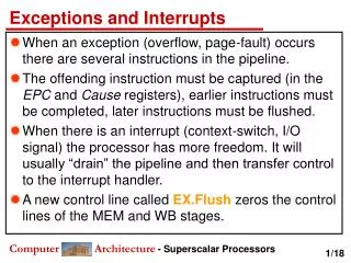
Important Slide Mask Set Maskable Hardware Interrupt Complete Current Instruction YES 1 Software Interrupt (SWI) Stack Pointer NO 0 Wait For Interrupt (WAI) Complete Current Instruction SP -6 Condition Code Register SP -5 Accumulator B SP -4 Accumulator A Store MPU Registers to SP SP -3 Index Register (MS) YES SP -2 Index Register (LS) Hardware Interrupt Wait For Interrupt (WAI) SP -1 Program Counter (MS) NO SP Program Counter (LS) Maskable NO Set Mask (CCR4) (set to 1) YES Condition Code Register Mask Set 1 0 X I Load Interrupt Vector into PC BeginInterrupt Program (ISR) Interrupt Vector Clear Mask (CCR4) (set to 0) Interrupts: Flow Back to Main Program Kipp Schoenwald
Mask Set Maskable Hardware Interrupt Complete Current Instruction YES 1 Software Interrupt (SWI) NO 0 Wait For Interrupt (WAI) Complete Current Instruction Store MPU Registers to SP YES Hardware Interrupt Wait For Interrupt (WAI) NO Maskable NO Set Mask (CCR4) (set to 1) YES Mask Set 1 0 Load Interrupt Vector into PC BeginInterrupt Program (ISR) Clear Mask (CCR4) (set to 0) Interrupts: Flow: IRQ Example 1 Back to Main Program If I bit in CCR is not set (I=0) and IRQ goes low for at least φ2 cycle, the IRQ sequence is entered. Internal registers stored to RAM (SP). The IRQ mask bit set (I=1). Data at FFF2 gets loaded into PCH Data at FFF3 gets loaded into PCL PC contents go out on address bus during φ1. Contents of the location addressed enter instruction register and are decoded as first instruction of interrupt routine. If it is a more than 1-byte instruction, additional bytes enter MPU for execution. If not, go to next step After execution, step 7 is repeated for subsequent instructions. This is repeated until “RTI” is executed. RTI tells the MPU that service is complete and that it may reload the registers and continue the main program from where it left off. Kipp Schoenwald
Important Slide Interrupts: Applications: Example 2 Write a routine to interrupt the MCU after 5ms of elapsed time, assuming prescaler is 1. Use output compare (OC) five. TFLG1 EQU $004E /*OC5 flag*/ TIE EQU $004C /*OC5 enable*/ TCTL1 EQU $0048 /*OC5 condition*/ SECONDAD EQU $FFE4 /*OC reference location*/ TCNT EQU $0044 /*counter*/ TC5 EQU $005A /*OC5*/ TIOS EQU $0040 /*timer input capture or output compare select*/ ORG $1000 /*begin routine at a chosen address*/ SEI /*set the I bit of the condition code register*/ LDAA %0010 0000 STAA TIOS /*configures port 5 as output compare (default is 0)*/ STAA TFLG1 /*clear previously set OC5 flag*/ STAA TIE /*enable OC5 Interrupt*/ configure ports as input or output LDAB %0000 1100 STAB TCTL1 /*OC condition: PA5 = high (for a successful compare)*/ LDX #$2000 /*$2000 is the address where you chose to put your ISR*/ STX SECONDAD /*stores this address “pointer” to the address that OC refers to. High byte (20) $FFE4, and Low byte (00) FFE5*/ LDD TCNT /*Loads current value of counter*/ ADDD #$9C40 /*adds 40,000cycles (5ms) to the current time (this equals the time when the ISR is to be run)*/ STD TC5 /*stores this value to be compared*/ CLI /*clear the I bit of the condition code register*/ Kipp Schoenwald
Outline • Interrupts • Vectors and Vector Table • Flow Chart • Applications • Example 1 • Example 2 • Priorities • Interrupt Stack • Thermistors • Theory • Applications • Opto-isolators • Theory • Applications • Phototransistors • Theory • Applications
Interrupts: Stack • The Stack Pointer Register holds the location of the top of the stack at all times. • When the CPU detects an interrupt the contents of the register are pushed on the stack. • After completion of the interrupt the saved registers are retrieved from the stack. The first register pushed onto the stack will be the last register pulled from the stack.
RTN LO RTN HI Y LO Y HI X LO X HI ACC A ACC B CCR • RTN – address of next instruction in Main Program, upon return from interrupt. • X LO and Y LO are the low bytes of X and Y registers. • X HI and Y HI are the high bytes of X and Y registers. • ACC A and ACC B are the accumulators. • CCR is the Code Condition Register Interrupts: Stack Interrupts: Stack Joseph Storey
Stack Pointer before Interrupt RTN LO Higher Address First Pushed In Last Pulled Off RTN HI Y LO Y HI X LO X HI ACC A Last Pushed In First Pulled Off Lower Address ACC B Stack Pointer after Interrupt CCR Interrupts: Stack Interrupts: Stack Joseph Storey
Interrupt Types Presents Maskable VS. Non-Maskable Interrupts: Priorities Joseph Storey
Non-Maskable Interrupts • 6 Non-Maskable Interrupts • Always interrupts program execution • Priority over Maskable Interrupts. • Not subject to global masking • Sets the X and I bit of the CCR when serviced Interrupts: Priorities Joseph Storey
Non-Maskable Interrupts • Priority of Non-Maskable Interrupts • POR of RESET pin • Clock monitor reset • COP watchdog reset • XIRQ interrupt • Unimplemented instruction trap • Software interrupt (SWI) Interrupts: Priorities Joseph Storey
Reset Forces MCU to: Assume set of initial conditions Begin executing instructions at an assigned starting address Like interrupts, resets have a vector to define the starting address of code to be run Unlike interrupts, they do not return to original code location Resets have different vectors to allow execution of individualized code Interrupts: Priorities Joseph Storey
When a reset is triggered: The address from the vector is loaded into the program counter S, X, and I bits are set in the CCR MCU hardware is initialized to reset state Check for any interrupts that have occurred Interrupts: Priorities Joseph Storey
Clock Monitor Reset Protects against clock failure Set by CME control bit If enabled, system resets if no clock edges are detected within a set period. Computer operating Properly (COP) Reset Protects against software failures (infinite loops, etc) When enabled (NOCOP bit in CONFIG register), resets if free-running watchdog timer rolls over $FFFF Timer rate is set in the OPTION register. System E-clock is divided by 215 and further scaled by 1, 2, or 4 Interrupts: Priorities Joseph Storey
XIRQ Externally triggered PE0 pin low = XIRQ interrupt Sets X and I bits RTI returns the X and I bits to original states prior to execution Interrupts: Priorities Joseph Storey
Opcode Trap and SWI Very low priority Any enabled interrupt source pending prior to the initialization of Trap or SWI will take precedence. Once process has begun neither can be interrupted. Interrupts: Priorities Joseph Storey
Maskable Interrupts • 27 Maskable Interrupts • Sets I bit in CCR when serviced • Automatically cleared by RTI interrupt • Follows default priority, but any one Maskable Interrupt can be elevated using HIPRO (Higher Priority) Interrupts: Priorities Joseph Storey
Maskable Interrupts Priority of Maskable Interrupts • IRQ • Real-Time Interrupt • Standard Timer Channel 0 • Standard Timer Channel 1 • Standard Timer Channel 2 • Standard Timer Channel 3 • Standard Timer Channel 4 • Standard Timer Channel 5 • Standard Timer Channel 6 • Standard Timer Channel 7 • Standard Timer Overflow • Pulse Accumulator A Overflow • Pulse Accumulator Input Edge • SPI transfer Complete • SCI system • ATD • Port J • CRG PLL Lock • CRG Self Clock Mode • Flash • CAN Wakeup • CAN Errors • CAN Receive • CAN Transmit • Port P • PWM Emergency Shutdown • VREG LVI Discussed in Timer Lecture Interrupts: Priorities Joseph Storey
IRQ Only external maskable interrupt signal IRQE bit on IRQCR Register IRQE=1: Falling Edge Sensitive IRQE=0: Low Level-Sensitive Peripheral Subsystems (all other Maskable Interrupts) Flag bit and interrupt enable bit ATD, Timers, PWM, serial communications, etc. Interrupts: Priorities Joseph Storey
Interrupts: Priorities Highest Priority Interrupt (HPRIO) • HPRIO register moves one maskable interrupt to top of priority list • Cannot change priority of non-maskable interrupts • Procedure to increase priority of maskable interrupt: • Set I bit to disable maskable interrupts • Write low byte of interrupt vector to HPRIO • Clear I bit to re-enable maskable interrupts Joseph Storey
Address: $001F • PSEL[7:1] – Priority Select Bits (HPRIO) • Selects one interrupts source to be elevated • Can only be written while I-bit in the CCR is set and maskable interrupts turned off • Write the low byte of the maskable interrupt vector to HPRIO to elevate that maskable interrupt to the highest priority • Ex: writing $DE to HPRIO elevates the Standard Timer Overflow to highest priority (Standard Timer Overflow vector = $FFDE) Interrupts: Priorities Joseph Storey
Interrupts • Vectors and Vector Table • Flow Chart • Applications • Example 1 • Example 2 • Priorities • Interrupt Stack • Thermistors • Theory • Applications • Opto-isolators • Theory • Applications • Phototransistors • Theory • Applications Outline
Thermistor - Temperature sensitive resistor • Their change in electrical resistance is very large and precise when subjected to a change in temperature. • Thermistors exhibit larger parameter change with temperature than thermocouples and RTD’s. • Thermistor - sensitive • Thermocouple - versatile • RTD – stable • Generally composed of semiconductor materials. • Very fragile and are susceptible to permanent decalibration. Thermistor Stephen Hunte
.095” DIA. MAX. #32 TINNED COPPER WIRE 3” LONG TEFLON INSULATION TEFLON TUBE .11 DIA. MAX. 2” MIN. • One of many available probe assemblies Thermistor Probe Stephen Hunte
Most thermistors have a negative temperature coefficient (NTC); that is, their resistance decreases with increasing temperature. • Positive temperature coefficient (PTC) thermistors also exist with directly proportional R vs. T. • Extremely non-linear devices (high sensitivity) • Common temperature ranges are –100 oF (~-75 oC) to +300 oF (~150 oC) • Some can reach up to 600 oF Thermistor Characteristics Stephen Hunte
= • An individual thermistor curve can be very closely approximated by using the Steinhart-Hart equation: T = Degrees Kelvin R = Resistance of the thermistor A,B,C = Curve-fitting constants • Typical Graph Thermistor (sensitive) V or R RTD (stable) Thermocouple (versatile) Thermistor R-T Curve T Stephen Hunte
Temperature Measurement • “Wheatstone bridge” with selector switch to measure temperature at several locations Thermistor Applications Stephen Hunte
variable resistor for setting desired temperature relay thermistor high gain amplifier Temperature Control • Resistor is set to a desired temperature (bridge unbalance occurs) • Unbalance is fed into an amplifier, which actuates a relay to provide a source of heat or cold. • When the thermistor senses the desired temperature, the bridge is balanced, opening the relay and turning off the heat or cold. Thermistor Applications
Operation similar to traditional transistors • Have a collector, emitter, and base • Phototransistor base is a light-sensitive collector-base junction • Small collector to emitter leakage current when transistor is switched off, called collector dark current Phototransistor Background Stephen Hunte
Phototransistor Package Types Stephen Hunte
A light sensitive collector base p-n junction controls current flow between the emitter and collector • As light intensity increases, resistance decreases, creating more emitter-base current • The small base current controls the larger emitter-collector current • Collector current depends on the light intensity and the DC current gain of the phototransistor. Phototransistor Operation
The phototransistor must be properly biased Basic Phototranstor Circuit
Adjust baffle length to obtain a specific detection range • Use infrared components that won’t be affected by visible light • Use ~ 220 ohm resistors for LED’s • Use multiple sensors in a row to detect narrow obstacles Phtotransistor Summary
They must be properly biased • They are sensitive to temperature changes • They must be protected against moisture • Hermetic packages are more tolerant of severe environments than plastic ones • Plastic packages are less expensive than hermetic packages PhtotransistorSUmmary Stephen Hunte
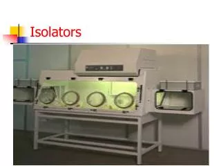
Optoisolator Background • Operation similar to relays • Used to control high voltage devices • Excellent noise isolation because switching circuits are electrically isolated • Coupling of two systems with transmission of photons eliminates the need for a common ground Optoisolator Background Stephen Hunte
Glass dielectric sandwich separates input from output Optoisolator Construction Stephen Hunte
Input Stage = infrared emitting diode (IRED) • Output Stage = silicon NPN phototransistor Optoisolator Schematic Stephen Hunte
Kipp Schoenwald kipp.schoenwald@gatech.edu • Stephen Hunte huntesteve@yahoo.com • Joseph Storey jstorey3@gatech.edu References Wikipedia.org Bishop R., Basic Microprocessors and the 6800 Contact Info