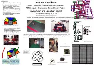
Autonomous Visual rover
Sean Day Diante Reid Liem Huynh. Autonomous Visual rover. Project Overview. To create a vehicle that autonomously follows a moving object using color detection To design a low cost, mobile robot that can track objects based on image processing


Autonomous Visual rover
E N D
Presentation Transcript
Sean Day Diante Reid Liem Huynh Autonomous Visual rover
Project Overview • To create a vehicle that autonomously follows a moving object using color detection • To design a low cost, mobile robot that can track objects based on image processing • Implement all of the parts using the Atmel microcontroller • Track any color specified by the user
Requirements • Operate solely on 7.2 V Ni-Cad battery for at least 1 hour • Keep a minimum of 10 inches away from target at all time. • Have a dimension of no more than 12x15 inches • Track object within color range “0 80 0 80 50 255 “
Environment SensorsManager Controller CMUCam2+ Top Level Diagram Centroid and ServoLocation TargetLocation Images Target Maxbotix LV-EZ2 UltrasonicSignals PWM TargetRange Environment Actuators Software Hardware PWM
Microcontroller - Arduino • ATMEGA328 • USB Interface • Cross-platform • Easy to program • Open source • Well documented
Microcontroller Specs • Operating Voltage : 5V • Digital I/O : 8 Pins • PWM: 6 Pins • Analog Input : 6 Pins • Flash Memory : 32kB • Clock Speed : 16 MHz • Communication : UART
Printed Circuit Board • PCB123 software • $100 student credit from sunstone • Prototyped on the Arduino board • 2 layer design • Using through hole and surface mount techniques
Image Processing Goals • Color detection • Ability to distinguish between specified color and other colors in environment • Detect centroid of specified object
Blob Detection • Middle Mass • Determines if a group of connecting pixels are related to each other by surroundings • Efficient in identifying separate objects in a scene
Image Processing Techniques • Edge Detection • Canny detection • Edges are areas where a jump in intensity from one pixel to the next occurs • Able to reduce the amount of data processed by filtering out useless information
CMOS vs. CCD Sensor CMOS CCD (charge coupled device) • Transistor based • Flexible design • Average picture quality • Low power consumption • Low Price • Analog device • Rigid design • Excellent picture quality • Power hungry • Very Expensive
Choosing a Vision System • CMUcam1 • CMUcam2 • CMUcam3 • AVRcam • Logitech QuickCam Orbit AF Webcam + RoboRealm
CMUcam2+ Vision Sensor Performs image processing duties for AVR Track user defined color blobs at up to 50 Frames Per Second Track motion using frame differencing at 26 Frames Per Second Gather a 28 bin histogram of each color channel Process Horizontally Edge Filtered Images
Why CMUcam2+ • Compact Size • Frame Buffering • Affordable price • Multiple Servo Control • User Support • Histograms
CMUcam2+ Software • Open Source Programmable • CMUcamGUI • Allows user to see from camera’s perspective
Voltage Regulation • All parts on AVR can run off of 5volts DC • Stepping Down 7.2 Volt battery • LM7805 regulator
Purpose is to keep AVR within 10 inches of target object Be able to fit on front bumper Will not loose the target object Low power consumption Ultrasonic Sensor Objectives
Maxbotics Ultrasonic Sensor • Maxbotics EZ2 • Will easily fit on bumper • Only draws 2mA of current • Easy to interface
Interfacing the Sensor • Pulse Width Modulation • 147 microseconds/inch • Analog Input • (Vcc/512)/inch • Communication • RS-232 Serial • Predetermined distance controlled by C progam
H-Bridge • Pololu High-Power Motor Driver 18v15 • 70A stall current • 1.3” x 0.8” • 15A continuous output • Max PWM frequency 40Hz
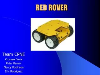
Chassis • 4 wheel drive • 2 front turning wheels • 2 rear wheels for going backward and forward • 1 DC motor • 1 Hobby servo • Rooms for expansion
DC Motor • Speed • 19,200 Rpm • Stall Current • 32A • No Load current • 1.3A • Operating Voltage • 3.6 to 6V
HiTec HS-311 Servo • Pan, Tilt, Steering • Max speed • .15sec/60° • Stall Torque • 42 -49 oz/in • Operating Voltage • 4.8-6.0V
Sensors Manager • getRange() • Returns range from Ultrasonic Sensor in inches • getCentroid() • Returns centroid location of target in x and y format • getPan() • Returns location of panning servo • getTilt() • Returns location of tilting servo
Centroid tracking • Tracking the object’s centroid 1 44 88
Coordinate Transformation 128, 0° • CMUcam to Body alignment • Body Frame, CMUcam Frame Servo Positions 46, -90° 210, 90° NegativeStop Positive Stop β Offset = 44 sin( β ) Centroid_B = Centroid_C + Offset
Navigation Flowchart Initialization ObjectFound? no Enter Search Mode yes no Centroid < 34 Centroid > 54 Good Detection? ForwardLeft ForwardRight Reverse yes yes no no yes else Object's range = 10 inches? Object's range <=10 inches? Forward Straight Stop yes yes
Search Mode • If no detection is found, AVR will go into search mode • Pan from negative stop to positive stop (180°) yes Object Found? no No detection Pan left Servo Pos > -90° & < 0? yes Exit no no yes no Servo Pos < 90°? Pan right Object Found? yes
Fault-tolerance • AVR stores the last 10 detections into an array: 1 for hit 0 for miss • Confident level is defined by taking the average of the stored values • If confident level > 70% then it’s a good detection 1 1 1 0 0 1 1 0 1 1 Confident level= 70% Good Detection!!
Proportional Controller Input Output + P (Range) Plant - Error • Variable speed depends on range from target • P gains need to be tuned • All control process is done through software
Testing • DC Motor/ H-bridge test • Range Finding Test • CMUcam2+ Pan and Tilt Test
Testing • Locomotion test with ultrasonic sensor stationary target • Locomotion test with ultrasonic sensor moving target • Locomotion test with CMUcam2+ with stationary target • Locomotion test with CMUcam2+ with moving target • Locomotion test with all sensors
Thank you, feel free to ask any questions…please come next door for demo