Download

1 / 8
120 likes | 590 Views
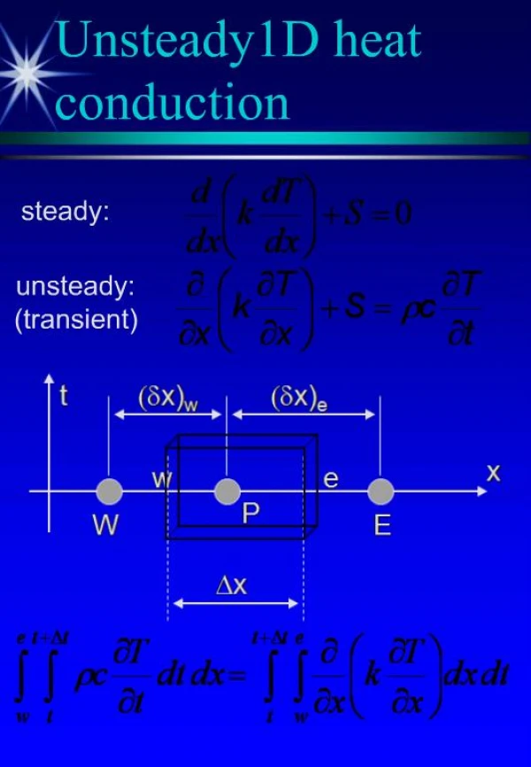
Role of Heat Conduction in a Jominy End Quench Design Project ME EN 340 Fall 2010. Stephen Cluff Dikshya Prasai. Jominy End Quench Test for Hardenability.

E N D
Role of Heat Conduction in a Jominy End QuenchDesign ProjectME EN 340Fall 2010 Stephen Cluff Dikshya Prasai
Jominy End Quench Test for Hardenability Hardenability: The ability of steel to form martensite upon quenching. Steels with low hardenability cannot form martensite deeper within material because of slow conduction of heat from interior (martensite requires rapid cooling to form) We sought to show the role that conduction plays in a Jominy end quench test of hardenability. We did this by performing the test, measuring the hardness along the length of the quenched sample, and comparing the plot of hardness vs. distance from quenched end with the plot of required cooling time vs. distance from insulated end. We insulated all faces but the quenched face to simplify the heat conduction problem. Our sample was 1018 steel, 1 in. in diameter, and 4 in long. Detailed description of apparatus and calculations can be supplied on demand.
Performing the Test The test was performed using a simple apparatus in the heat treatment lab. The hoses were hooked up to a sink that supplies water at 11 °C. The volume flow rate was measured and used to calculate the velocity of the water. The water shot out from the pipe and into the hole where the steel was held during the quenching process. The Steel sample was austenized by heating uniformly to 1500 °F, and then held with an insulating material over the hole that the water shot through. The sample was held there until it was at room temperature.
Collecting Hardness Data Once the sample was quenched, a flat face was ground along the length of the sample for the hardness testing. The scale used to measure the hardness was the Rockwell A scale. Ninety hardness readings were collected for the plot of hardness vs. distance from the quenched end of the rod. The data collected was input into Microsoft Excel and used to create the plot. The plot created is displayed with the results of our project.
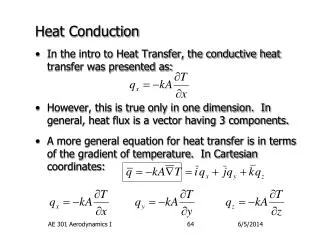
Solving the Heat Transfer Problem The goal of the project was to compare the time it took for different parts of the rod to cool to room temperature with the hardness at that location. This was done by solving the transient conduction problem. Our model was simplified by considering all faces but the quenched face to be insulated. The first step was to find a correlation equation for impinging jet flow of a single round nozzle, in order to calculate a convection coefficient. This correlation was found in an article by Holger Martin entitled “Heat and Mass Transfer between Impinging Gas Jets and Solid Surfaces.” In this article Martin describes the figure shown above, which was used to calculate a Nusselt number and the convection coefficient. With this information, T(x,t) was found with the above equation. The approximate analytical solution was valid, as Fo > 0.2 was held true.
Results of Comparison The calculations were done to show how much time it took for the material to cool to 25°C at each location where the hardness was measured. This was done by using the known T(x,t) to find the time for T(x,t) = 25 at each location x. The results show that greater time to cool corresponds with the end that has the lower hardness readings. This is just as expected. The time to cool was much faster than calculated, however. The figure to the left measures time in minutes. The actual time to cool to room temperature was closer to 5 minutes. This is most likely due to the fact that the sample was not perfectly insulated as assumed.