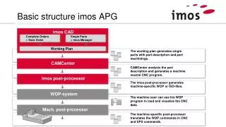
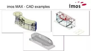
imos MAX - CAD examples
imos MAX - CAD examples. i mos CAM - part types. Type A: Panel part with drilling , milling , sawing , etc. CAM APG: Automatic generation of all machinings and tools (3 or 4-Axis). CAM APG: Automatic generation of adjustment-axis machinings (3+2 Axis).

imos MAX - CAD examples
E N D
Presentation Transcript
imos CAM - parttypes Type A: Panel partwithdrilling, milling, sawing, etc. CAM APG: Automatic generation of all machinings and tools (3 or 4-Axis) CAM APG: Automatic generation of adjustment-axis machinings(3+2 Axis) Type B: Panel partwithadjustment-axis milling (3+2 axis) Type C: Processed panel with grooves and formatting CAM APG/ MAX: Automatic/semi-automatic CNC data generation (depends on process) Type D: Bended plane with formatting CAM MAX: semi-automatic generation of CNC data for part and form Type E: Free form partswithsurfacemachinings CAM MAX: Manual processforgenerating CNC data
imos MAX - essentials 5 axis kernel For every operation the toolpath is calculated by machining-, guiding- and boundary surfaces with taking account of: • 5 axis milling strategy • 5 axis settings • machine and tool information Boundary Surface = Guiding Surface Machining Surface
5 axiskernel - millingstrategies Drilling: Wire Frame: Surfaces:
5 axiskernel - millingstrategies Trianglemesh: Hobbing:
5 axis kernel - axis guidance Machine axis: Tool contact point: Tool axis:
5 axis kernel - lead in/lead out Lead in/out of tool: Geometry gaps: Trails:
5 axis kernel - collisioncontrol Collision tool: Collision part: Collision-avoiding strategies:
5 axis kernel - unmachinedpart Unmachined part from CAD: Automaticallygeneratedunmachinedpart:
imos MAX - KITs The 5 axis kernel offers approximately 800 settings for creating machining operations. To create a simple formatting operation at least 32 settings have to be defined in the 5 axis Kernel. The imos KITs are pre-defined machining operations (e.g. formatting, grooves, roughing) and preserve just the essential settings from the 5 axis kernel in the user interface. This makes it possible to simply select the surfaces that shall be machined for a formatting. The imos KITs contain all necessary settings as default-values. In the user interface tools can be selected the lead in/lead out or the machining depth can be configured. KITs Benefits: • simple creation of complex 5 axis machinings • guided creation of machining operations • less effort in programming 5 axis machinings / lower time expenditure • less training course expenditure with pre-defined machining operations
imos MAX - KITs Pre-defined machining operations: • drilling • 3D polyline • roughing/ finishing • pocket/ groove milling • formatting • island milling • milled drilling • free-form pockets
imos MAX - CNC simulation Toolpath: Material removal: Cinematic:
imos MAX Worksteps: • create program • select machine • part positioning • create operation • select KIT • pick geometry • define parameters • start simulation
imos MAX Workstep 1: • create program • selectmachine • part positioning • create operation • select KIT • pick geometry • define parameters • start simulation
imos MAX Workstep 2: • create program • select machine • Part positioning • create operation • select KIT • pick geometry • define parameters • start simulation
imos MAX Workstep 3: • create program • select machine • part positioning • create operation • select KIT • pick geometry • define parameters • start simulation
imos MAX Workstep 4: • create program • select machine • part positioning • create operation • select KIT • pick geometry • define parameters • start simulation
imos MAX Workstep 5: • create program • select machine • part positioning • create operation • select KIT • pick geometry • define parameters • start simulation