Download
1 / 77
780 likes | 902 Views
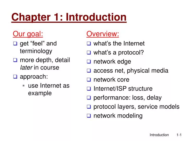
Our goal: get “feel” and terminology more depth, detail later in course approach: use Internet as example. Overview: what’s the Internet what’s a protocol? network edge access net, physical media network core Internet/ISP structure performance: loss, delay

E N D
Our goal: get “feel” and terminology more depth, detail later in course approach: use Internet as example Overview: what’s the Internet what’s a protocol? network edge access net, physical media network core Internet/ISP structure performance: loss, delay protocol layers, service models network modeling Chapter 1: Introduction Introduction
Chapter 1: roadmap 1.1 What is the Internet? 1.2 Network edge 1.3 Network access and physical media 1.4 Network core 1.5 Internet structure and ISPs 1.6 Delay & loss in packet-switched networks 1.7 Protocol layers, service models 1.8 History Introduction
millions of connected computing devices: hosts = end systems running network apps communication links fiber, copper, radio, satellite Different transmission rates routers: forward packets (chunks of data) router workstation server mobile local ISP regional ISP company network What’s the Internet: “nuts and bolts” view Introduction
“Cool” internet appliances Web-enabled toaster + weather forecaster IP picture frame http://www.ceiva.com/ World’s smallest web server http://www-ccs.cs.umass.edu/~shri/iPic.html Internet phones Introduction
protocolscoordinate communication Who gets to transmit? What path to take? What message format? e.g., TCP, IP, HTTP, FTP, PPP Internet: “network of networks” loosely hierarchical public Internet Vs private intranet Internet standards RFC: Request for comments IETF: Internet Engineering Task Force What’s the Internet: “nuts and bolts” view router workstation server mobile local ISP regional ISP company network Introduction
communication infrastructure enables distributed applications: Web, email, games, e-commerce, file sharing communication services provided to apps: Connectionless unreliable connection-oriented reliable What’s the Internet: a service view Can you give an analogy of this in real life services Introduction
human protocols: “what’s the time?” “I have a question” introductions … specific msgs sent … specific actions taken when msgs received, or other events network protocols: machines rather than humans all communication activity in Internet coordinated by protocols What’s a protocol? protocols define format, order of msgs sent and received among network entities, and actions taken on msg transmission, receipt Introduction
a human protocol and a computer network protocol: TCP connection response Get http://www.awl.com/kurose-ross Got the time? 2:00 <file> time What’s a protocol? Hi TCP connection request Hi Q: This one trivial. Can u think of a more complex case? Introduction
Chapter 1: roadmap 1.1 What is the Internet? 1.2 Network edge 1.3 Network access and physical media 1.4 Network core 1.5 Internet structure and ISPs 1.6 Delay & loss in packet-switched networks 1.7 Protocol layers, service models 1.8 History Introduction
network edge: applications and hosts network core: routers network of networks access networks, physical media: communication links A closer look at network structure: Introduction
end systems (hosts): run application programs e.g. Web, email client/server model client host requests, receives service from always-on server e.g. Web browser/server; email client/server peer-peer model: minimal use of dedicated servers e.g. Skype, BitTorrent, KaZaA The network edge: Any idea how? Introduction
Goal: data transfer between end systems Connection: prepare for data transfer ahead of time Request / Respond set up “state” in two communicating hosts TCP - Transmission Control Protocol Internet’s connection-oriented service TCP service[RFC 793] reliable, in-order byte-stream data transfer loss: acknowledgements and retransmissions flow control: sender won’t overwhelm receiver congestion control: senders “slow down sending rate” when network congested Network edge: connection-oriented service Introduction
Goal: data transfer between end systems same as before! UDP - User Datagram Protocol [RFC 768]: connectionless unreliable data transfer no flow control no congestion control App’s using TCP: HTTP (Web), FTP (file transfer), Telnet (remote login), SMTP (email) App’s using UDP: streaming media, teleconferencing, DNS, Internet telephony Network edge: connectionless service Introduction
Chapter 1: roadmap 1.1 What is the Internet? 1.2 Network edge 1.3 Network access and physical media 1.4 Network core 1.5 Internet structure and ISPs 1.6 Delay & loss in packet-switched networks 1.7 Protocol layers, service models 1.8 History Introduction
Q: How to connect end systems to edge router? residential access nets institutional access networks (school, company) mobile access networks Keep in mind: bandwidth (bits per second) of access network? shared or dedicated? Access networks and physical media Introduction
Dialup via modem up to 56Kbps direct access to router (often less) Can’t surf and phone at same time: can’t be “always on” Residential access: point to point access • ADSL: asymmetric digital subscriber line • up to 1 Mbps upstream (today typically < 256 kbps) • up to 8 Mbps downstream (today typically < 1 Mbps) • FDM: 50 kHz - 1 MHz for downstream 4 kHz - 50 kHz for upstream 0 kHz - 4 kHz for ordinary telephone Introduction
HFC: hybrid fiber coax asymmetric: up to 30Mbps downstream, 2 Mbps upstream network of cable and fiber attaches home to ISP router homes share access to router deployment: available via cable TV companies Residential access: cable modems Introduction
Residential access: cable modems Diagram: http://www.cabledatacomnews.com/cmic/diagram.html Introduction
Cable Network Architecture: Overview Typically 500 to 5,000 homes cable headend home cable distribution network (simplified) Introduction
server(s) Cable Network Architecture: Overview cable headend home cable distribution network Introduction
Cable Network Architecture: Overview cable headend home cable distribution network (simplified) Introduction
C O N T R O L D A T A D A T A V I D E O V I D E O V I D E O V I D E O V I D E O V I D E O 5 6 7 8 9 1 2 3 4 Channels Cable Network Architecture: Overview FDM: cable headend home cable distribution network Introduction
DSL is point to point Thus data rate does not reduce when neighbor uses his/her DSL But, DSL uses twisted-pair, and transmission technology cannot support more than ~10Mbps Cable Modems share the pipe to the cable headend. Thus, your data rate can reduce when neighbors are surfing concurrently However, fibre optic lines have significantly higher data rate (fat pipe) Even if other users, data rate may still be higher DSL vs Cable Modem The debate / competition continues … Introduction
company/univ local area network (LAN) connects end system to edge router Ethernet: shared or dedicated link connects end system and router 10 Mbs, 100Mbps, Gigabit Ethernet LANs: chapter 5 Company access: local area networks Introduction
shared wireless access network connects end system to router via base station aka “access point” wireless LANs: 802.11b/g (WiFi): 11 or 54 Mbps wider-area wireless access provided by telco operator 3G ~ 384 kbps Will it happen?? GPRS in Europe/US router base station mobile hosts Wireless access networks Introduction
Typical home network components: ADSL or cable modem router/firewall/NAT Ethernet wireless access point Home networks wireless laptops to/from cable headend cable modem router/ firewall wireless access point Ethernet Introduction
Chapter 1: roadmap 1.1 What is the Internet? 1.2 Network edge 1.3 Network access and physical media 1.4 Network core 1.5 Internet structure and ISPs 1.6 Delay & loss in packet-switched networks 1.7 Protocol layers, service models 1.8 History Introduction
mesh of interconnected routers the fundamental question: how is data transferred through net? circuit switching: dedicated circuit per call: telephone net packet-switching: data sent thru net in discrete “chunks” The Network Core Introduction
End-end resources reserved for “call” link bandwidth, switch capacity dedicated resources: no sharing circuit-like (guaranteed) performance call setup required Network Core: Circuit Switching Analogy: When president travels, a CS path set up. Introduction
network resources (e.g., bandwidth) divided into “pieces” pieces allocated to calls resource piece idle if not used by owning call (no sharing) Network Core: Circuit Switching • dividing link bandwidth into “pieces” • frequency division • time division Introduction
Example: 4 users FDM frequency time TDM frequency time Circuit Switching: FDM and TDM Introduction
FDM Vs TDM • What are the tradeoffs? • (Dis)Advantage of dividing frequency ? • (Dis)Advantage of dividing time ? Introduction
Numerical example • How long does it take to send a file of 640,000 bits from host A to host B over a circuit-switched network? • All links are 1.536 Mbps • Each link uses TDM with 24 slots/sec • 500 msec to establish end-to-end circuit Let’s work it out! Introduction
Another numerical example • How long does it take to send a file of 640,000 bits from host A to host B over a circuit-switched network? • All links are 1.536 Mbps • Each link uses FDM with 24 channels (frequencies) • 500 msec to establish end-to-end circuit Let’s work it out! Introduction
each end-end data stream divided into packets user A, B packets share network resources each packet uses full link bandwidth resources used as needed Bandwidth division into “pieces” Dedicated allocation Resource reservation Network Core: Packet Switching resource contention: • aggregate resource demand can exceed amount available • Packets queue up • store and forward: packets move one hop at a time • Node receives complete packet before forwarding Introduction
Sequence of A & B packets does not have fixed pattern, shared on demand statistical multiplexing. TDM: each host gets same slot in revolving TDM frame. D E Packet Switching: Statistical Multiplexing 100 Mb/s Ethernet C A statistical multiplexing 1.5 Mb/s B queue of packets waiting for output link Introduction
Thoughts on tradeoffs between packet switching and circuit switching? Which one would you take? Under what circumstances? Why? Compare Introduction
1 Mb/s link each user: 100 kb/s when “active” active 10% of time circuit-switching: 10 users packet switching: with 35 users, probability > 10 active less than .0004 Packet switching allows more users to use network! Packet switching versus circuit switching N users 1 Mbps link Q: how did we get value 0.0004? Introduction
Great for bursty data resource sharing simpler, no call setup Excessive congestion: packet delay and loss protocols needed for reliability, congestion control Q: How to provide circuit-like behavior? bandwidth guarantees needed for audio/video apps still unsolved (chapter 7) Is packet switching a “slam dunk winner?” Packet switching versus circuit switching Why? Introduction
Takes L/R seconds to transmit (push out) packet of L bits on to link or R bps Entire packet must arrive at router before it can be transmitted on next link: store and forward delay = 3L/R (assuming zero propagation delay) Example: L = 7.5 Mbits R = 1.5 Mbps delay = 15 sec Packet-switching: store-and-forward L R R R more on delay shortly … Introduction
Goal: move packets through routers from source to destination we’ll study several path selection (routing) algorithms (chap 4) datagram network: destination address in packet determines next hop routes may change during session analogy: driving, asking directions virtual circuit network: packet carries tag (virtual circuit ID), tag determines next hop fixed path determined at call setup time, remains fixed thru call routers maintainper-call state Packet-switched networks: forwarding Introduction
Packet-switched networks Circuit-switched networks FDM TDM Datagram Networks Networks with VCs Network Taxonomy Telecommunication networks • Datagram network is not either connection-oriented • or connectionless. • Internet provides both connection-oriented (TCP) and • connectionless services (UDP) to apps. Introduction
Chapter 1: roadmap 1.1 What is the Internet? 1.2 Network edge 1.3 Network access and physical media 1.4 Network core 1.5 Internet structure and ISPs 1.6 Delay & loss in packet-switched networks 1.7 Protocol layers, service models 1.8 History Introduction
roughly hierarchical at center: “tier-1” ISPs (e.g., MCI, Sprint, AT&T, Cable and Wireless), national/international coverage treat each other as equals NAP Tier-1 providers also interconnect at public network access points (NAPs) Tier-1 providers interconnect (peer) privately Internet structure: network of networks Tier 1 ISP Tier 1 ISP Tier 1 ISP Introduction
Seattle POP: point-of-presence DS3 (45 Mbps) OC3 (155 Mbps) OC12 (622 Mbps) OC48 (2.4 Gbps) Tacoma to/from backbone peering New York … …. Stockton Cheyenne Chicago Pennsauken Relay Wash. DC San Jose Roachdale Kansas City … … … Anaheim to/from customers Atlanta Fort Worth Orlando Tier-1 ISP: e.g., Sprint Sprint US backbone network Introduction
“Tier-2” ISPs: smaller (often regional) ISPs Connect to one or more tier-1 ISPs, possibly other tier-2 ISPs NAP Tier-2 ISPs also peer privately with each other, interconnect at NAP • Tier-2 ISP pays tier-1 ISP for connectivity to rest of Internet • tier-2 ISP is customer of tier-1 provider Tier-2 ISP Tier-2 ISP Tier-2 ISP Tier-2 ISP Tier-2 ISP Internet structure: network of networks Tier 1 ISP Tier 1 ISP Tier 1 ISP Introduction
“Tier-3” ISPs and local ISPs last hop (“access”) network (closest to end systems) Tier 3 ISP local ISP local ISP local ISP local ISP local ISP local ISP local ISP local ISP NAP Local and tier- 3 ISPs are customers of higher tier ISPs connecting them to rest of Internet Tier-2 ISP Tier-2 ISP Tier-2 ISP Tier-2 ISP Tier-2 ISP Internet structure: network of networks Tier 1 ISP Tier 1 ISP Tier 1 ISP Introduction
a packet passes through many networks! local (taxi) T1 (bus) T2 (domestic) T3 (international) Tier 3 ISP local ISP local ISP local ISP local ISP local ISP local ISP local ISP local ISP NAP Tier-2 ISP Tier-2 ISP Tier-2 ISP Tier-2 ISP Tier-2 ISP Internet structure: network of networks Tier 1 ISP Tier 1 ISP Tier 1 ISP Introduction
Chapter 1: roadmap 1.1 What is the Internet? 1.2 Network edge 1.3 Network access and physical media 1.4 Network core 1.5 Internet structure and ISPs 1.6 Delay & loss in packet-switched networks 1.7 Protocol layers, service models 1.8 History Introduction